Superlift's Website
(This is just for reference only; always follow the instructions provided by Superlift). Be careful with the torsion bars as they store a lot of energy -- always work with them unloaded. They can be dangerous. The following is what I did:
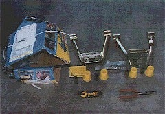
I installed some Superlift 1.5" - 3" Upper Control Arms (part number S6065) on the Pathfinder over the holidays. I paid US $215 + shipping for the arms, CDN $119 (US $85?) for the coils. The arms were ordered from Rocky Mountain Suspension Products.
Other parts in the kit include a sticker, bushing sleeves and some bolts which I suspect are upper balljoint bolts (there isn't any mention of them in the instructions). The instructions are pretty good (no pictures though!), but it'll definitely help to have a factory or Haynes manual for pictures to refer to. Also, a couple of torque figures aren't included in the instructions.
The actual lift is achieved by adjusting the torsion bars. You can achieve pretty much the same lift effect by cranking up the torsion bars -- small lifts (say less than 1") can probably be accommodated this way without needing a kit. When you increase the lift, the tires begin to camber negatively (top of tire moves inward towards the body) and the upper ball joint also takes on more of an angle from horizontal. These effect can cause wear on the ball joint as well as take the camber out of the alignment range, causing uneven tire wear.
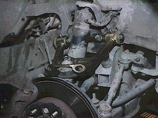
The Superlift UCA kit replaces the factory stamped upper control arms with heavy-duty welded units. Their function is to modify the upper ball joint angle back to horizontal and to provide a little more length in the arms so that the camber alignment can be brought back into specification.
There is no increase in wheel travel with the kit (as is the case with all replacement UCA kits). The stock frame-mounted bumpstops are what limit the suspension travel, and the Superlift arms will contact the bumpstops at the same range of travel. As a result, when you lift the suspension, you eat up your suspension's downward travel. The Nissan IFS probably has about 7" of travel or so, and the factory position is about the middle of this range. Hence when you crank it up 3" downwards, you pretty much run out of downward travel and will be riding on the bumpstop continously which makes for a harsh ride and probably shortens the life of the suspension components. Also, if you've previously cranked up the torsion bars, you won't get any increase in height due to the new arms.
Superlift claims no change in ride due to topping out of the bumpstop up to 2.5" of lift, with the ride getting harsher past this point to the 3" limit. I'm shooting for 1.5 - 2". With the current 1" approx. over stock height, I still have upper bumpstop clearance left.
It may be possible to adjust the bumpstop position to allow for a bit more downward travel. This can be done in two ways: replacing the factory bumpstop with a lower one, or by switching the UCA from one side to the other. I could replace the rubber bumpstop to a poly one to gain the clearance, but I like the progressive nature of the rubber one instead.
Swapping the arms won't be a very hard operation and both sides are symmetrical. The latter works because the bumpstop extension (welded to the arm) is only on one side of the UCA. By switching arms, the bumpstop will contact the arm itself. Both arms and spindles are identical, so they can be switched quite easily. This will of course increase the suspension travel.If anybody has done this, I would love to know!
Installation notes(This is just for reference only; always follow the instructions provided by Superlift). Be careful with the torsion bars as they store a lot of energy -- always work with them unloaded. They can be dangerous. The following is what I did:
- Raise the truck on jackstands and remove the tires.
- Unload the torsion bars by unbolting the adjusters until they are loose.
- Remove the shock absorber (upper nut and a lower bolt) -- I was able to use a large wrench to keep the shock from rotating while I undid the upper stud nut, otherwise the shock just twists around. With adjustable shocks, you don't have to remove the electrical connector which isn't easy -- I just placed the shock out of the way on top of the shock mount; it works great as a shelf.
- Support the wheel hub assembly so it doesn't flop over when the upper arm is removed -- I used the regular jack.
- Loosen the UCA spindle bushing nuts -- it's easier to do it now than later, since they won't move!
- Unbolt the ball joint from the arm (4 bolts).
- Remove the spindle-to-frame bolts (2 of them). Keep the alignment shims (if any) that are behind the spindle for later and don't mix them up.
- Remove the A-arm assembly with spindle.
- Remove the bushing nuts and washers from the spindle.
- Press out the spindle from the A-arm. Easier said than done! You should probably be able to find an auto suspension or 4x4 shop with a hydraulic press to do this. I tried using my Hi-Lift jack as a press to no avail -- those bushings are stuck in there. Finally, I resorted to burning the bushings out (see later comments).
- Slip the supplied metal bushing sleeves onto the spindle. Lubricate the insides of the poly bushings with grease. Reassemble the spindle inside the Superlift A-arm and bolt the assembly up. You might as well torque the assembly to spec now since you probably won't be do so once you install it due to the tight clearance. Install the grease fittings with thread locking compound. NOTE: The supplied bushing sleeves seemed to be too large (they were longer than the poly bushings), so I decided to reuse the old sleeves which were the right length.
- From this point on, the installation is the reverse of the removal process. Use thread locker on the 4 ball joint bolts. Don't forget to do the other side as well!
- The missing torque figure: shock absorber lower bolt (70 ft-lb).
- Double check that the suspension will travel and steer without problem. Grease the bushings.
- Re-tension the torsion bars to their previous settings, replace tires, and lower vehicle. You're done...but wait...
- In order to crank up the bars fully, you'll probably need to reindex the torsion bars. I set this by unloading the torsion bars, removing the bar anchor, setting the desired tensioner length, and replacing the bar. I set the exposed length of the tensioner (from tip of tensioner to the frame crossmember) to about 2.75". The factory measurement spec calls for about 1.9" - 2.3". Right now, the tensioner bolt pokes out about 1/2" under the crossmember with my current 1" over stock lift , but I still have some more cranking adjustment to go so the bolt may indeed be protected by the crossmember once I'm finished. I used a 2.5" measurement on the other side, so I can compare which is the better figure. At this point, 2.5" seems to be better as it still allows for adjustment, but the bolt head does not stick below the crossmember, which makes it vulnerable to trail damage.
- Go for an alignment. The suspension toe-in is definitely affected by the lift. The camber, according to Superlift, will likely not need adjustment at about 2.125" - 2.625" lift height, which is probably where the kit was designed for. All the more reason to go for a 2" lift, I suppose. With this logic, maybe lower lifts will result in too much positve camber and thus require removal of shims.
In order to burn out the bushings, I used the propane torch and a screwdriver. I set the bushings on fire and scraped at it with the screwdriver to remove the ashes. The bushing does not keep burning, so I had to keep the flame pointed at it. Eventually, I hollowed out enough of both bushings for the spindle to push out. Don't forget to do this outside as nasty black smoke and ashes are produced!
Installation was about 10 hours (solo) with figuring out how to extract the bushings, reindexing the torsion bar on one side, and full cleanup. The vehicle hasn't been cranked up to final height yet; I'll wait until the coils settle in and I can decide on the final parameters. I'll also need to reindex the other torsion bar.
In future, I will replace the swaybar end link. Right now it is a little short compared to what it should be. Probably another 3/4 to 1" extra length will make the swaybar ends more or less parallel to the A-arm.
Editor's note: This article was written by the previous editor, Martin Chung.
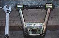 The Superlift UCAs seem to be very good quality construction with a yellow plated (zinc?) finish, and they come with greasable polyurethane bushings and with zerk grease fittings. |
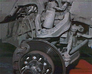
Pathfinder's right Independent Front Suspension (IFS) showing upper control arm, upper spindle, and adjustable shock. The upper ball joint is attached to control arm by four bolts. Spindle assembly is held by two spindle-to-frame bolts. |
The upper rubber bumpstop is also visible below the UCA bumpstop extension. |
|
|
Off-Road.com Newsletter Join our Weekly Newsletter to get the latest off-road news, reviews, events, and alerts! |
Follow @Off-Road
 Your Privacy Choices