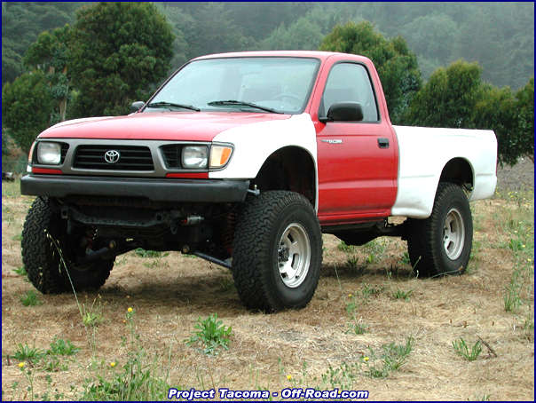
 Total Chaos Fabrication has developed a line of desert racing inspired long travel front suspension systems that are far more performance-oriented than any of the mainstream drop-bracket type lift kits. The Total Chaos 4WD/Prerunner Tacoma long travel setup provides 14"of vertical wheel travel; that's more than double the suspension travel of a stock Tacoma truck, and is achievable retaining the use of 4WD!
There is performance and ride quality to be gained from this type of suspension far beyond the bullshit drop bracket IFS lift kits out there. Why lift your truck more than you need to? Why only gain additional tire clearance and a minimal increase in performance off-road? Why modify a perfectly good truck to ride stiff and handle poorly? Total Chaos suspensions are built to actually perform off-road and by the same modifications, IMPROVE the handling and ride quality of your truck on-road. Here it is in a quick wrap-up: fit larger tires with minimal lift, gain additional ground clearance, increase suspension travel, significantly improved performance on and off road.
The Tacoma installation can easily be completed in a driveway over a weekend and is almost entirely bolt-on except for a couple tabs (included) that need to be welded in-place to mount the limiting straps after the installation if finished. Ride height is adjustable from a minimum of 3" lift over stock and has been designed to clear 33" tires on full compression of the suspension.
This article is not intended to be an instructional step-by-step installation for the novice mechanic because although the modifications being discussed are fairly straightforward, if you are not familiar with the concepts and mechanics of the parts involved, you should probably leave any modifications related to the suspension and steering of your truck to professional mechanics.
 |
The Total Chaos long travel kit comes with all of the parts needed for a complete installation, including Grade 8 hardware and detailed installation instructions with computer illustrated diagrams. The Total Chaos parts list includes; new upper and lower A-arms (3.5" wider than stock per side), upper Uni-balls & press-in adapter slugs, new polyurethane bushings with laser cut washers, replacement upper shock mounts, extended braided stainless steel brake lines, steering link extensions, adjustable limit straps, and even a drill bit & tap for remounting the bump stops. All the parts come powder coated or plated for durability and to resist corrosion. |
 The only additional parts required are two 2.5" x 8" coil-over shocks and two 16" x 500lb coil springs. If the truck is going to retain 4WD, it will only require the addition of stock Tundra CV axle shafts. We ordered a pair of 2.5" x 8" Swayaway remote reservoir shocks and Eibach coil springs from Kartek in Corona, CA. Kartek is the best source we have found for anything related to performance off-road vehicles, from major suspension components like the ones we ordered to specialized fabrication pieces like shock tabs, Uni-balls & rod ends in a ton of sizes and for many applications.
Because the new suspension will sit 7" wider than a stock truck, fiberglass front fenders must be installed in order to provide clearance and coverage for the tires. Check out the
Glassworks installation article published last month to see how easy that modification is.
This Total Chaos suspension system has been designed for trucks based on the 4WD chassis and is engineered to work with stock Tundra CV axle shafts and automatic hubs. Because we have manual hubs, we will be using a hybrid of old and new parts, but we'll explain more about that next month. We are still researching our options and honestly, just couldn't get all of the parts in time to publish this month. The front differential, front drive shaft and skid plates been removed in all of the following images for reasons of clarity.
 |
 |
| Note the quality of construction, illustrated here in the top and bottom views of the fully boxed and gusseted lower A-arm. There are two lower shock tabs included; the forward mount is used with the coil-over shock as shown in this article while the rear serves as a mounting point for the limiting strap and also allows customers to add an additional pair of shocks. The most benefit can be had by the addition of an 8" stroke, position sensitive bypass shock on each side of the front suspension. |
 |
|
| Remove the stock front suspension from the truck one side at a time. Follow reasonable steps to remove the flexible rubber brake line, upper A arm, lower A arm, and CV axle assembly as one unit. It is necessary to remove the steering rack hardware in order to access the rearmost camber bolt in the lower control arm. It is not necessary to remove the steering rack entirely. Further disassembly of the suspension is required but is easiest to complete with the parts removed from the truck. Remove upper and lower control arms from the spindle, and remove the two bump stops from each of the lower A arms by unthreading them with a pair of large channel-lock pliers. |
Beginning the installation of new components one side at a time, complete the lower control arm assembly by installing the supplied polyurethane bushings and spacers. Use a liberal amount of general-purpose chassis grease during assembly and then remove any excess grease that will attract dirt and grime. Reinstall the two lower control arm camber bolts as shown and position them to a neutral setting before tightening. Reinstall and tighten the steering rack hardware.
 |
 |
| The rubber suspension compression bump stops that were part of the stock lower control arm assembly are relocated to the frame rail and reused with the Total Chaos arms because they are much softer than polyurethane and resist cracking under hard use. Total Chaos supplies the drill bit and tap that are required to mount the bump stops. First mark and drill a hole in the center of each circle where the bump stops were designed to make contact. Then use the supplied tap to thread each hole. |
 |
|
| The bump stops are clearly labeled F and R on each of the front and rear bump stops. Install the two stock rubber bump stops with the included washers in the frame rail as shown. |
 |
 |
| The upper ball-joint must be pressed out of the spindle. We fabricated this simple tool to accomplish the job using two pieces of scrap angle iron, a few old nuts and bolts and a short piece of tubing to make a simple press. |
 |
 |
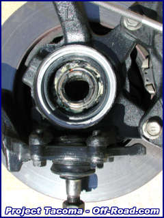
| Since we are not reinstalling the front differential at the same time as the new suspension, we had to temporarily plug the Spindle. We removed the top and bottom of a conveniently sized soup can and used silicone to create a seal against the elements that can later be removed when 4WD axles are reinstalled. |
 |
 |
| These images show the upper control arm and the new bushings that are installed using the stock hardware. Note the welds, the gussets at every junction of the arm, and quality all the way down to the 1/4" laser cut washers. |
 |
 |
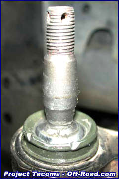
| The massive 1" Uni-ball shown here in detail points out exactly what kind of abuse these components are designed to endure. The adapter slug is a press fit, and is installed with the same tool used for removal. Compare that image to the stock ball joint, shown here on full extension. |
 |
 |
| The lower ball-joint is retained, held in the spindle and shown here in detail and on full extension. The lower ball-joint has more angularity than the upper ball-joint and can cycle through the entire range of suspension travel without binding. |
 |
|
| Because the suspension control arms are 3.5" wider per side, the steering links from the rack and pinion steering box must be extended by the same amount. The link extensions simply thread into place, in between the ball-joint and the original link. The steering joint does not suffer any binding throughout the suspension travel, and through lock-to-lock steering. |

| The instructions note that there can be interference between the stock steering stop on the spindle and the replacement lower control arm. That interference can be seen as the small gouges in the lower control arm that are shown in the right side of the image. On the spindle in the left side of the image, we have ground away enough material to eliminate any further contact. |
| | |
| The completed installation of the replacement control arms and stock spindle should now be cycled and checked for any interference or binding. See the difference in travel afforded by the new components as compared to the stock arms. |

| Install the flexible braided stainless steel brake lines supplied with the kit and then bleed the brake system. When removing the stock lines, make sure to use a metric flare wrench because the fittings are soft and easy to strip. |

| Install the upper shock mount adapters onto the coil-over shocks as shown and then install the shock into the upper mounts using the three Grade 8 bolts, washers and locking nuts. |
| | |
| Thread the upper coil seat onto the shock body and then slide the coil spring over the shock. Install the lower coil seat and make sure to decompress the remote reservoir before trying to compress the shock and install the lower mount. Only let enough nitrogen charge out to allow the shock to be compressed, and do not forget to recharge the nitrogen chamber after the installation is complete. The reservoir has a floating piston inside that can be damaged if the truck is driven without a nitrogen charge in the chamber. |
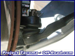
 If you are using remote reservoir coil-over shocks, the reservoirs will need to be mounted in any number of ways depending on your particular vehicle and preferences. We chose this location forward on the frame-rail, using a low profile 90-degree fitting on the shock body as the best place to mount our reservoir canisters. Kartek sells the reservoir mounts that we used for only a few dollars each, including high quality hose clamps.
| | |
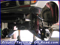
| The completed suspension is shown here from the front and side angles, with the coil springs installed. Depending on your workflow you might want to check for tire-to-body clearances before installing the coil springs because you will need to cycle the suspension to full compression. |
| | |
| Limiting straps are used to control suspension travel as it approaches full extension. They are designed to stretch approximately 20% and so to function as progressive stops. The lower mounting point is fixed, and the upper is adjustable by the threaded clevis mount. When positioning the tab to be welded on the frame-rail the suspension should be at full extension, and the limiting strap placed in-line with the suspension cycle-path. Adjust the clevis nuts so that there is room for the limiting strap to be tightened, because it is not being positioned under any load, and will not limit travel correctly if left unadjusted. |
| This is what the completed suspension should look like on full extension with all of the components in place. The only thing further, if not done already is to remove the coil spring, reinstall the shock and then cycle the suspension to full compression with the wheel and tire installed. The truck will need to be set to ride height and then taken to an alignment shop. We set our ride height to 3" of lift (5" of shock shaft exposed), which is the lowest the truck can be made to sit without limiting the extension travel. The ride height is dictated by spring preload and without the right amount of it, the spring will flop around at full extension, potentially damaging the shock, the spring, or even possibly falling out. |

| The long travel Tacoma suspension is designed to clear 33" tires. We can verify that this setup will properly clear 33" x 10.5" x 15" tires mounted on 15" x 8" rims with 4.5" of backspacing on full compression and through lock to lock steering. Glassworks Unlimited supplied the fenders we used, and more information about that installation can be found in the article published last month about their fiberglass products. |

| The front fender is attached to the inner body by two bolts behind the corner lamp. We found that the rearmost of those bolts interferes with the tire at full compression and needs to be removed. The bracket is held to the body by two nuts that are easily accessed. The remaining hardware is more than sufficient to mount the fender securely. The fiberglass on our front fender also needed to be trimmed slightly further forward to avoid contact while turning. |

| Our tire cleared the Glassworks fender and the inner body at the top of the wheel well with room to spare. If you're already thinking that 35" tires would fit in there, wait until you see how close the tire rides to the fire-wall. |
| | |
| Tire clearance at the fire-wall is tight, but can be made adequate with one simple modification involving a tube of silicone and a light hammer or mallet. We only had to fold the body seam over to the outside of the truck to eliminate any tire-to-body contact. Run a generous bead of silicone down the inside of the fold before it is hammered over completely so that water and debris cannot easily rust out that area. Remove the excess silicone and give the outside edge of the fold a light coat of primer to protect the metal where the paint inevitably chipped while hammering on it. |
Currently, Total Chaos offers long travel front suspension products for Tacoma and Tundra trucks in addition to a range of other Toyota two and four wheel drive trucks all the way back to 1986 (the first year 4WD Toyota IFS trucks were produced). They also make a line of long travel front suspension products for IFS Nissan trucks and a front suspension designed for straight axle Jeep Cherokee (XJ) truck competing in the desert Jeep Speed series.
Next, we are turning our attention to the rear suspension and installing 62" Deaver leaf spring and Swayaway piggyback reservoir shocks using Total Chaos spring hangers, spring mounts and the brand new Total Chaos shackles.
We'll also be taking a look back at the steps we've taken to get our front suspension to where it is now, and comparing the cost vs. performance at different steps along the way. Comparing shocks, spring rates, stock width and long travel front suspensions, etc.
Coming soon, there will be a parts, source and current price list for all of the components used in the buildup so far.
Total Chaos Fabrication
909.737.9682
www.chaosfab.com
Email:
chaosfab@aol.com
159 North Maple St. Suite J
Swayaway
818.700.9712
www.swayaway.com
info@swayaway.com
20724 Lassen St.
Chatsworth Ca 91311
Kartek Off-Road
909.737.7223
www.kartek.com
offroad@kartek.com
Talk about our Tacoma Project in the
Tacoma BBS
Send us
Email about Project Tacoma


 Your Privacy Choices