!DOCTYPE html PUBLIC "-//W3C//DTD HTML 4.01 Transitional//EN">
August 2001 --
Removal of the 22-RE from the 4-Runner was pretty much
identical to removal of the 7M-GE from the Supra drain the fluids,
disconnect the lines, and pull it out. The only thing special I had
to do was to support the front of the transmission with some tie
straps. I needed to be able to roll the vehicle in and out of my
garage throughout the swap, and I was hoping I could complete the
swap without dropping out the tranny/transfer case.
Installing the
7M-GE
Motor
Mounts
 |
|
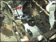
The Supra mounts lined up
relative to where the 4-Runner mounts did. |
After the 22-RE was removed, I was able to start
on the fun stuff. The first thing I did was to make sure that the
Supra bellhousing would bolt up to the transmission, and sure
enough it fit perfectly. My first major project was the motor
mounts- I had no idea how they would line up or how I would mount
the engine if they didn't. This is where having the extra 7M-GE
block was really nice- after swapping all of the accessories over
to the new engine, I stripped the old one down to the block, and
used that to figure out the mounts. With everything removed, it was
significantly lighter and much easier to maneuver within the tight
space. As soon as I got it in I realized that the mounts were not
even close- the Supra mounts lined up 6 inches behind the 4-Runner
mounts. After what I had heard from others who had done the swap, I
was surprised, as theirs had lined up much closer. After studying
it for an hour or two (read: lying underneath the vehicle sipping a
beer!), I decided to cut out the mounts from the Supra and weld
those to the 4-Runner frame.
Using an angle
grinder and a reciprocating saw (what I wouldn't have paid for a
plasma cutter!), I cut the mounts out of the Supra. I then spent
quite a bit of time determining the position of the motor- I wanted
it to sit high in the engine bay so that there would be as much oil
pan clearance as possible, but there were other factors involved.
At the rear of the engine, there is very little space between the
back of the head (and heater hoses/vacuum fittings) and the top of
the transmission tunnel/firewall. Raising the engine too much would
cause clearance problems there. Also, obviously, the hood had to
fit back on! So, I spent a lot of time measuring and moving the
engine around until I was positive that it would clear the hood and
the firewall, but still leave as much space as possible underneath.
With the engine correctly positioned, I used a cardboard template
to mock-up how I would need to trim the Supra mounts so they could
be welded to the frame. After trimming and fitting the mounts, a
friend and I tack welded them in with the block in place, removed
the block, and finished welding them in. They did need some
gusseting for additional strength, but I think they will work
OK.
 |
|
Here are what the welded in
Supra mounts look like after some grinding and fab
work. |
**NOTE** After I had already cut out the
stock motor mounts (the day after, actually), I learned from others
who have completed this swap that you CAN use the stock truck
mounts. To do this, you need to obtain the engine brackets from a
5M-GE engine, which was available on 1985 and older Supras. These
will attach further forward on the block and will line up much
better with the 4-Runner's mounts. You can then use the rubber
mounts from the 22-RE and bolt them to the 5M-GE engine
brackets.
After installing the flywheel
and clutch, I attempted to drop in the complete engine for the
first time. This is where the extra length of the I6 makes things a
little difficult- with the transmission still in place, it is
impossible to fit the engine between the front of the bellhousing
and the radiator support. After trying it from a couple of angles,
I realized that I would have to move the tranny out of the way. I
didn't want to remove it completely and have to re-install it by
myself, so I supported it on a jack, removed the rear driveshaft,
and unbolted the cross member. Still supported by the jack, I was
able to slide it backward about 6 inches but still leave it pretty
much in place. After that, I was able to carefully maneuver the
engine in place. Once the clutch/flywheel cleared the edge of the
bellhousing I was able to slide the tranny forward again and
re-attach the cross member.
 |
|
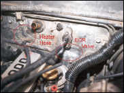
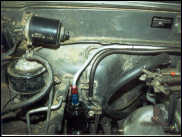
Here are the two areas on the
firewall, which need to be pounded in to make enough clearance for
the EGR valve and the heater hose. |
The next step was bolting up the engine to the
bellhousing. For those of you who haven't attempted this, this can
either be extremely easy or the most frustrating experience of your
life. The splined input shaft must fit in the splines of the
clutch, and the tip of the shaft must line up with the pilot
bearing. To accomplish this, both the engine and transmission must
not only line up side to side, but also they must be at exactly the
same angle front to rear. Add to this the fact that you can't
actually see any of the parts you are trying to line up, and the
weight of the engine, and it can get pretty ugly. After messing
around with it for about an hour, I finally got lucky and the input
shaft popped into place- I didn't know exactly how I did it, but
there was no way I was going to let it come apart again. I quickly
installed a couple of the bolts to keep it in place, and crawled
out from underneath to finally get a look at the installed
engine.
After attaching the engine mounts
and removing the chain hoist, I was able to finally see how
everything lined up. I noticed several things immediately; most of
them revolving around the fact that clearance at the front and rear
of the engine was almost non-existent. The two places that I would
need to do something about before I went any further were at the
firewall- both the EGR valve and the heater hose which exits at the
rear of the head were hitting the firewall. With the movement of
the engine, there would be problems later on. I investigated
blocking off that section of the heater hose and tapping into the
side rail tube, but after looking at a schematic, I realized that
is the main outlet of coolant from the block to the heater unit.
The only other option to increase the clearance was to create an
indentation in the firewall so the hose would not rub. This was
also the only solution for the EGR valve, so after re-attaching the
engine hoist and removing the motor mounts, I lowered the
engine/tranny about 6 inches so I had access to the firewall. A few
minutes of pounding with a BFH and a quick spray of paint and I
could raise the engine back into position and re-attach the motor
mounts. The clearance was still tight, but I was positive that
nothing would actually be rubbing. With the heavy manual labor part
of the project done, I could start working on getting everything
connected.
 |
|
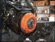
The slick-looking Centerforce
clutch ought to grab the added horsepower and put it directly to
the tires. |
CLUTCH
Installation
of the Centerforce II clutch was pretty straightforward. Just
before the engine was installed, I attached the flywheel and clutch
following the factory service manual's and Centerforce's
instructions. The flywheel had been resurfaced, and new throw-out
and pilot bearings were used. After the engine was in place, I
installed the Supra slave cylinder and soft line to the
bellhousing. The soft line was secured to the firewall using a
line-clip. Because the clutch was now on the opposite side of the
vehicle, I would need to run a new line from the master cylinder.
NAPA sells different lengths of hard line with the correct
fittings, so it was simply a matter of measuring the length I
needed and bending the line to fit. After adding fluid to the
reservoir and adjusting the pedal height and free-play to the
correct specs, I bled the system. I was worried that the clutch
pedal effort was going to increase, but it feels no different than
stock.
RADIATOR/COOLING
I had known from the start of the swap that the
radiator and cooling system were going to be a challenge. So, I
wasn't disappointed. Immediately after installing the engine, I
knew that it was going to be difficult to fit a radiator in the
space between the pulleys and the radiator support, let alone a
radiator and fan. I had ordered a new 3-core radiator from Downey
that was designed for the Chevy 4.3L V6 swap. It bolts up to the
stock mounts, but extends 5" lower than the stock radiator. Plus,
the upper and lower hose fittings are on the correct sides for the
new engine. The radiator fit (barely), but the lower hose fitting
hit on the power steering pump pulley and needed to be trimmed back
about 2". I also realized that the upper hose would be very close
to the alternator pulley, and with the movement of the engine could
create a problem. There was plenty of room between the top of the
radiator and the hood, and moving the radiator up 1" would create
plenty of clearance for the upper hose. I removed the radiator,
drilled 4 new holes 1" lower than the existing ones, and
re-installed it. For the lower hose, I used the stock Supra hose
which fit perfectly. For the upper hose I used a hose with a
90-degree bend that I found at Pep Boys and cut to length.
 |
|
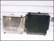
Here's the difference in the
stock 4-Runner radiator on the left and the new radiator at right.
Cooling should not be a problem. |
I had hoped that I would have enough room between
the radiator and engine to fit a thin profile electric fan, but
there was no chance of that. The next option was to go with pusher
fans mounted on the outside of the radiator. I looked into the
available options, and decided on Flex-a-lite model #230. The 230
comes with 2, 12" fans that move 2500 cubic feet/minute. Although a
pusher fan is not as efficient as a puller fan (approximately 30%
less due to the air escaping around the edges of the fan), I think
that with the larger radiator and the twin fans the engine will run
cool enough. All Flex-a-lite fans come with mounting hardware that
allows installation either through the radiator fins or using
supplied mounting brackets. This model also comes complete with an
adjustable thermostat (180-240 F) and AC relay, as well as all the
required wiring hardware. After unpacking the fan, I realized how
thin they really were (2 5/8"). For most applications, a puller
could have been used, but I had less than 2" clearance.
The next step was to determine how to mount the
fan. The AC condenser (the thing that looks like a small radiator
in front of the "real" radiator) would definitely have to be moved,
but that was OK- see AC section below. After that was removed, I
lined up the fan unit with the radiator and started thinking. The
fan shroud/housing is made of a very strong nylon, and comes with 6
reinforced holes for mounting. For the upper fan mounts, the two
outer holes in the fan shroud lined up with the upper radiator
support. I marked and drilled holes, and bolted the shroud to the
radiator support. For the lower mounts I realized there was a
tapped bolt hole (from the stock bumper) in the center of the lower
radiator support that lined up with the middle hole in the fan unit
that I could use. For the two outer mounts, I used the supplied
mounting brackets, and welded tabs to the frame cross-member. I did
need to trim the upper radiator support a bit to clear the fan
blades, but once attached, there was no flex in the fan unit at all
and the blades spun freely.
 |
|
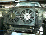
The Flex-A-Lite twin pusher fan
is mounted in front of the radiator. This monstrous beast will do
the job - reliably. |
As I mentioned above, this unit came with an
adjustable thermostat and AC relay. These are connected to a
control box that I mounted to the radiator, and the temperature
control bulb was run to the upper radiator hose. Using the supplied
hardware, I mounted and taped the bulb inside the hose. The wiring
of the fan is very simple- as I will not have AC for at least a
little while, all I had to do was connect the fan leads to the
control box, and connect a power and ground wire. Once I get
everything up and running, I plan on connecting a manual switch to
the fan so I can turn it off for water crossings.
For the heater hoses, the main difficulty lay in
the fact that the heater switch and inlet/outlet hoses were on the
opposite sides for the two engines. This meant that I had to make a
lot of extra bends in the hoses to get them routed correctly. I got
the schematics for the two systems from the local Toyota dealer,
which helped immeasurably. I noticed from the schematics that the
return hard line attached to the block had outlets on both sides of
the block- I assumed for right- and left-hand drive versions.
Instead of blocking off the passenger side outlet and running the
return line to the driver's side as it was in the Supra, I ran the
line directly to the passenger's side hard line. For the rest of
the connections, I spent a lot of time behind the parts counter at
Pep Boys searching for hoses with the correct bends. I finally
found some that I thought would work, and with a couple of hose
connectors I patched everything together correctly.
EXHAUST
 |
|
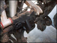
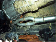
Here's the first section of the
custom exhaust coming out of the engine compartment just above the
differential mount. |
As the 7M-GE exhaust exits on the opposite side of
the vehicle, I had no idea how it could be routed until I got the
engine installed. After it was in, I realized that although it
would be tight, there was enough room to exit the engine
compartment just above the passenger's side front differential
mount and run alongside the tranny and transfer case just above the
front driveshaft. Another problem came up due to the IFS- the
torsion bars run just inside the frame rails, right where the
exhaust will run, making the available space for the exhaust even
tighter. Once it is past the transfer case, there is plenty of room
to cross over to the driver's side to clear the gas tank. The cat
and the muffler will be in the stock location.
 |
|
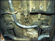
Here's another sectionof the
exhaust crossing over behind the transfer case. |
After doing some research into it, I decided to
run a 2 ¼" exhaust to a Turbo muffler- the non-turbo engine
needs some back-pressure to keep the low end power up. According to
the Supra guru's, the stock manifold flows pretty well, so I will
keep that and run the new exhaust from there. After getting some
recommendations for a good exhaust shop, I had the 4-Runner towed
there and explained what I wanted. Although they were a little
reluctant to get into a custom job at first, they ended up doing a
great job- especially since the front differential and driveshaft
were not installed for reference. They used the stock manifold and
the flange and first 6 inches of the down-pipe. From there, they
built a custom "Y" into a 2 ¼" pipe that ran past the
tranny/transfer case, crossed over to the driver's side, and back
to a Magna Flow turbo muffler. Behind the muffler, I just wanted a
short section of pipe pointing straight down to help keep the
exhaust from coming up into my bed through the shock holes.
FUEL
 |
|
T
he
fuel line comes off the fuel filter and over to the fuel
rail. |
After the exhaust was finished, I could determine
where to run the fuel lines. There was only a short section where
the lines ran close to the exhaust just before they bent upwards
into the engine compartment. They ran along the top of the frame,
and there was enough room to move them to the bottom of the frame
where they would be far enough away from the exhaust. There was
even a tapped hole already in the exact location to move the line
clip lower on the frame. Once in the engine compartment, I needed
to run two lines to the other side of the engine- a high pressure
line and a low pressure return line. For the pressurized line, I
wanted to run it in a location where there was the least chance of
it being damaged in case of an accident. I decided the best way was
to run a hard line above the bellhousing, securing the line to the
firewall with line clips to keep it from moving. Once to the other
side, I connected it to the Supra's soft line. The return line was
easy- I simply ran some 3/8" fuel hose alongside the pressurized
hard line over to the charcoal canister. I did replace the
4-Runner's fuel filter with a larger in-line Supra filter which I
mounted to the inner fender just below the charcoal
canister.
 |
|
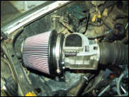
The air cleaner mounting
bracket secures the K&N filter to the passenger-side fender
well. |
INTAKE
As I tried
to fit in the stock intake, I realized there was no way that it
would fit- it was just too long. It consisted of a short length of
flexible tube, a large airflow drum, another short length of
tubing, the mass air flow sensor, and then a huge air box. I had to
take off at least 6 inches to get it to fit, and even then there
was no room for the huge air box. I trimmed the two sections of
tubing as short as possible, and started looking into options for
the air box. I had planned on switching to a K&N filter, and
when I started looking into them I realized that their fuel
injection performance kit (FIPK) would work great. It takes the
place of the air box, and not only is much smaller but because it
allows air intake from all directions it claims around a 10%
increase in HP. After picking one up, I connected everything up and
it fit- barely. I did have to remove the windshield washer
reservoir bottle, but that is a small price to pay. The FIPK comes
with an L-bracket to mount to a stock bolthole in the Supra- I
needed to shorten it about 2" so it would line up with the
4-Runner's battery tray. I marked and drilled a hole for the mount,
and used a sheet metal screw to attach it securely.
MISC. ISSUES
AC
- Once the engine was installed, I realized there was a
clearance issue with the AC compressor and the power steering box.
The 4-Runner's AC compressor was on the opposite side of the
engine, but the 7M-GE's compressor mounts right next to the
steering box, and the compressor hits it by about an inch. For the
time being, I am just going to run without AC. I also needed to
remove the condenser to mount the electric fans, so I am just going
to have to be hot for a while. Once I get everything up and
running, it will be an interesting project for the future. I have
no idea how I am going to solve it, but I am sure there is a
way.
Power Steering - Since the PS
pump for the 7M-GE is on the opposite side, I needed to run custom
lines from the pump to the steering box. I re-located the reservoir
to the passenger side, and had a local repair shop run custom
lines.
Vacuum hoses - As much as
possible, I kept the vacuum hoses intact during the swap. However,
the Supra was equipped with ABS and cruise control that the
4-Runner does not have, so I did have to re-route a couple of
hoses. I got a schematic from the Toyota dealership, which was
invaluable for this. Also, I had to move the line from the intake
manifold to the brake booster to clear the heater switch, but that
was pretty easy.
Accelerator Cable -
The 4-Runner cable was way too long, but luckily the Supra cable
was not only the perfect length but attached to the firewall and
the pedal exactly the same way, so it was simply a matter of
swapping them out.
4WD - As I
mentioned in the background article, I think I may be the first
person to try this swap with IFS. Now that the engine is in, I can
positively state that there IS a clearance issue with the IFS front
differential. It is not so much a matter of up and down clearance-
it is more a matter of a couple of inches side to side. The 22-RE
pan was offset towards the driver side so it cleared the diff- the
7M-GE pan is not offset. It would clear the diff if it were offset
only an inch or so, but it would take approximately 4 inches of up
movement to clear. At this point I am thinking it will take a
custom oil pan, or maybe a
dry sump to be able to get back 4WD. Those of you who have a
straight front axle will not have this problem. Again, it will be
an interesting project for the future.
Next Month
As of the time of
this article, the only thing that I still need to do to get it
running is the wiring. I don't think it will be too difficult to
get the engine wiring connected, but getting all of the gauges
connected may be a different story. I also need to figure out how I
will mount the battery and the ECU. Check back next month for the
complete info as well as my first impressions with the new
engine.
The Supra Swap - Part 1 Story -
Photo
Gallery 1
The Supra Swap - Part 2
Story - Photo
Gallery 2