SOLID AXLE (78-79) DANA 44 REBUILD
Note:
You can click on any image to download the FULL SIZE picture. To perform this rebuild, you should have a shop manual that lists torque specifications, a full size floor jack, two jack stands (3 ton minimum) , and a hub bearing nut tool. It would also be helpful to have a dial indicator with magnetic base and gear pattern grease.
-
Remove wheels and place front axle on jackstands. I like jacking under radius arm mounts, as front spring is directly over this point. -
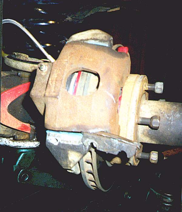
Remove one bolt from lower end of brake caliper bracket. This bolt may be frozen. Use "BP Blaster" (or your favorite penetrating oil) , allowing several minutes of soaking, to free bolt. Using a large screw driver, punch out shim located on lower side of brake caliper. The shim is two parts, make sure you have both when the parts fly off the back of caliper into never-never land (also note orientation to facilitate reinstallation). Pry on caliper near center of hub and remove caliper. Inner brake pad may still be there and will also need to be removed. Do not let caliper hang by rubber brake line. Removed tire can be pushed to just behind axle to rest caliper on. 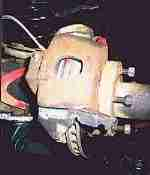
Note:
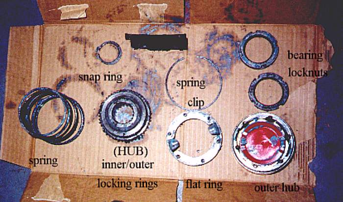
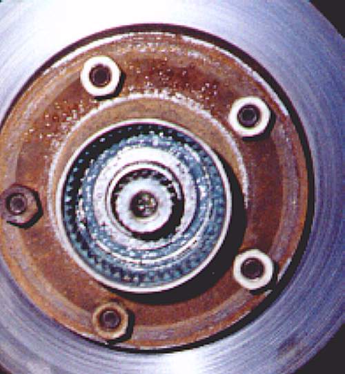
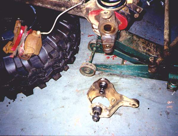
Ensure you have a clean piece of cardboard to place removed parts on. This cardboard will need to be moved later to get all the parts out of the way of debris falling off truck when you hammer at axle flange mounts.The figure to the right shows all the parts you will remove before rotor will come off. 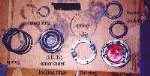
-
Using appropriate size (I have seen two different sizes) allen socket/wrench, remove six allen head bolts that hold hub in. Use rubber mallet to lightly tap hub on top until it comes off. -
I have seen 3 different hub locking mechanism's on 78-79 DANA 44 front axles. Two have a flat looking ring that hub allen bolts screw into. 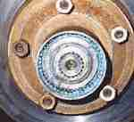
The aluminum hub locking mechanism makes it particularly hard to get at spring clip, but it is possible. After removing spring clip, remove flat ring for all steel setups. Aluminum casting will stay put for now. Warning:
Removing axle shaft snap ring may allow spring to force inside locking mechanism out of hub. (Usually on the floor will it where it will get all dirty)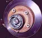
-
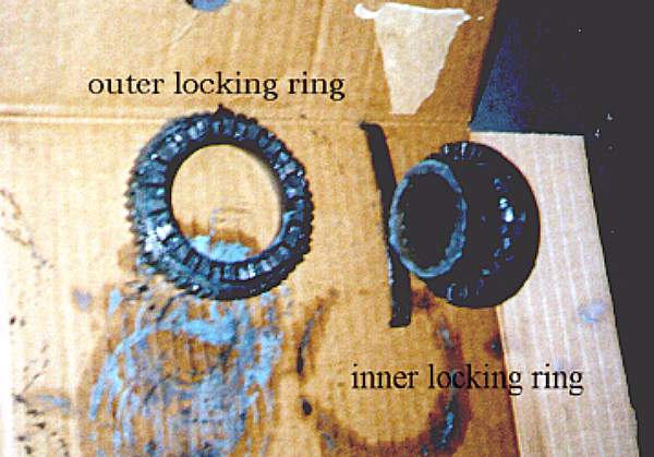
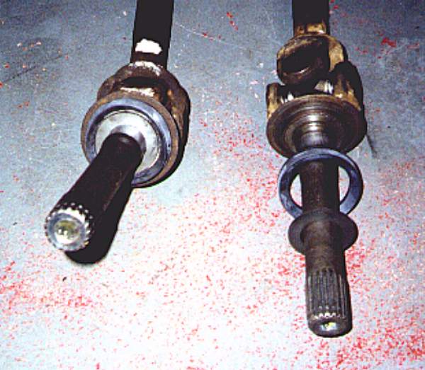
Using snap ring tool, remove snap ring on axle shaft. It may be necessary to push axle shaft towards outward side of vehicle. Shaft can be pushed outward from behind rotor, at steering universal joint. Remove inner and outer locking mechanism, being careful of spring pressure. Mechanism will consist of one of these; -
-
Inner and outer star wheel. (This mechanism hangs up easily and may not engage when hub is locked, if gummed up). -
Inner and outer parts that ride on each other, but engage with dog teeth facing side to side with respect to vehicle. (Best Setup, IMHO) 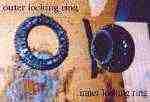
-
Inner metal star with aluminum outer part. (I now understand why some people break hubs, junk!!) One small phillips screw will need to be removed if aluminum casting is seen. With aluminum casting, spring is much smaller and presses against steel star located inside alum casting. Spring on all metal versions is much larger and creates a much larger force.
-
-
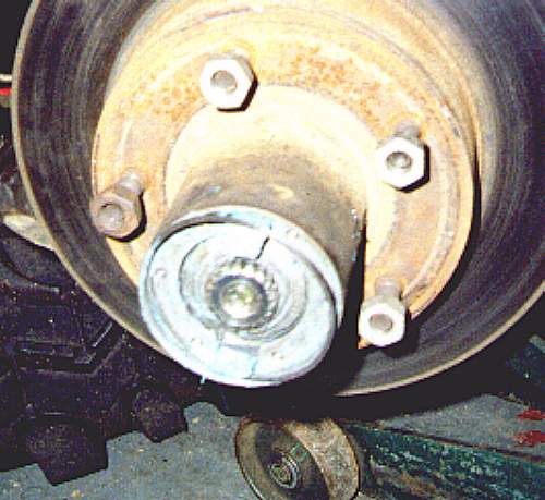
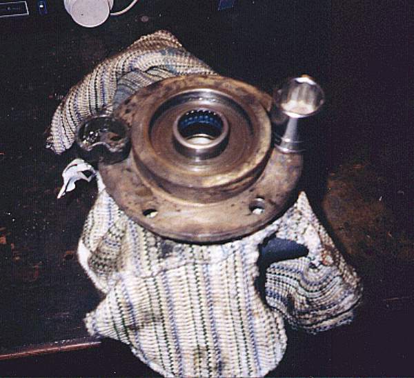
Using hub bearing nut tool, remove outer hub bearing nut. Ensure hub bearing nut tool has four indentations lined up with bearing nut. Using snap ring tool, remove locking alignment ring. Alignment ring has many small holes in it. Snap ring tool will fit in 2 of these small holes and can usually be freed by pulling straight out on snap ring tool. Note groove in axle flange and tab on ring. 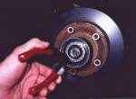
-
Again using hub bearing tool, remove inner hub bearing nut. 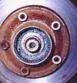
-
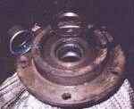
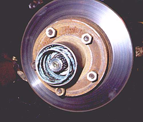
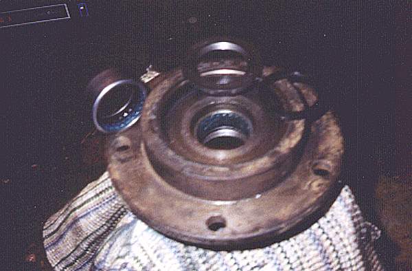
Rotor/hub assembly can now be removed. Outer bearing will be loose, but inner bearing will be held in by grease seal. Place rotor on two 2 x 4's with hub facing up. Use a hardwood dowel to punch bearing and grease seal out the bottom. Wipe off grease on axle flange and ensure bearing surfaces are not damaged. -
Inspect both bearings and races for wear, looseness and pitting. If you have never replaced bearings/races, now would be a good time. -
Get all parts moved to as far away from the truck as possible. Debris will be falling off fenders/frame during next removal process. Parts are covered with grease and will pick up this debris. -
Remove 5 nuts that hold axle flange/caliper bracket to steering knuckle. -
Using medium flat chisel and relatively large hammer, force chisel in between axle flange and caliper mount bracket. Use chisel at several different points around flange to pry it off evenly. If this is the first time you have ever removed flanges, it may take a large amount of force to remove them. Keep at it and they will come off. The studs you just took nuts off of can be pressed out to facilitate hub removal. Make sure nuts are screwed on in reverse and mounted flush with ends of studs if you use hammer to get studs out. I have personally not had to ever remove studs. One stud will hit ball joint and not come completely out. Dust shield may be slightly damaged by chiseling. Dust shield can be discarded for you off-roaders or pounded flat for reinstallation later. 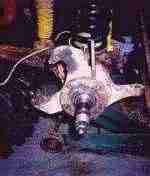
-
Axle shaft can now be pulled out. Do step 14 first if you are going to change fluid and/or axle seals. Care should be exercised, because axle seal is located directly on either side of differential. If you don't plan on replacing these seals, you don't want to damage them. If axle seals are not going to be replaced, go to step 24. 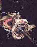
-
Remove all front differential cover bolts, except for the top most bolt, only loosen this bolt 2-3 revolutions. Pry open cover at bottom with screwdriver. Leave screwdriver in-between case and housing until fluid drains. Leaving cover on keeps dirt out of differential housing while fluid is draining. I let fluid drain at least an hour. -
Scribe an identification mark on differential bearing caps. These bearing caps have to go back exactly as they came out. You can't mix sides or flip them over. Engrave them any way you want so you will know which way they go back. 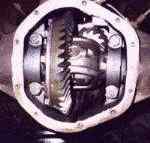
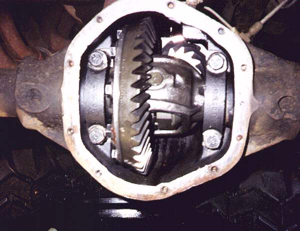
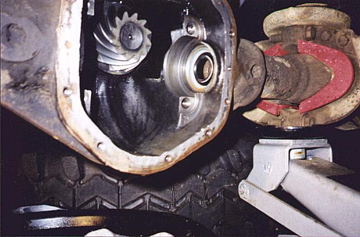
Remove 4 bearing cap bolts. Differential with ring gear can be pried out using a large screwdriver. Be careful not to pry on part of differential that is open. Damage to spider gears inside differential may result. Be sure to hold differential bearing races or they will fall on the floor. Differential bearing races can not be interchanged. 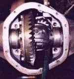
-
Tape an old spoon to a really long screwdriver or rod. Use this contraption to scoop out any built up mud/gunk inside bottom of axle tubes. -
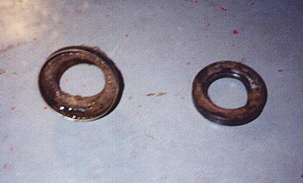
Axle seals are located to the left and right of where the differential bearing races were. These can be pried out with a big screwdriver. Ensure screw driver does not damage machined surface that differential bearing races fit into. Seals may need a decent amount of force to pry out. Seal is two parts, the seal and a metal guide that guides axle shaft through seal. Both parts must come out. 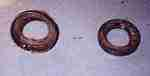
-
Ensure all dirt/gunk that has fallen into differential from pulling out seals is cleaned. Wipe out inside of axle tube where seal is to be re-installed. -
New seal may be different looking than old seal. Actual seal (Rubber) part may be smaller than what you have removed. Coat outside of seal assembly (metal part) with a thin covering of gasket maker. Using appropriate size socket (approx. 2.25" OD), force seal into housing until it is flush with end of axle tube. Wipe any excess gasket maker. 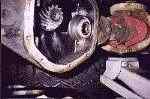
-
Ensure axle housing is clean of all debris and gasket maker is scraped off housing. Check ring gear, pinion gear and differential bearings/races for wear/damage. Install differential, ensuring bearing races are inserted equally. Fit will be very tight. Allowing one bearing race to be inserted deeper than the other will cock differential making insertion virtually impossible. When you have differential almost seated, you can tap on outer part of each race with a rubber hammer. Tap alternately on each side to ensure equal fit of races. -
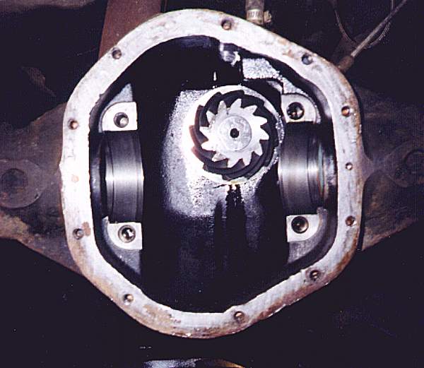
Apply LOK-TITE, red grade (#271) to differential carrier cap bolts. Install and torque to specification (80 ft.-lbs.). Check gear pattern with white grease and backlash if desired. These should not have changed. I have never personally checked this. Gear pattern should look like this. 
Note:
Rotate driveshaft and ensure ring gear and differential rotate freely. If binding is felt, differential bearing races are probably not seated correctly. -
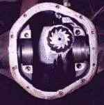
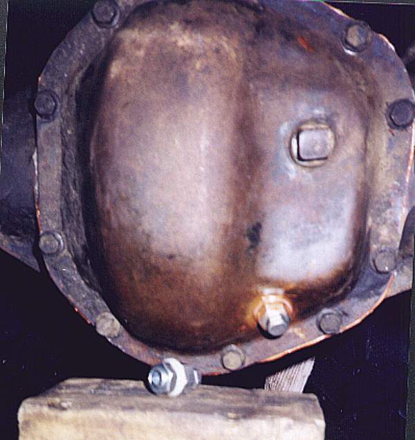
Clean gasket maker off differential cover. If desired, drain plug can be installed at approximate location seen below. Ensure no interference from differential internals will result from installing drain plug. I used a transmission drain plug I got at Pep Boys. I also used gasket maker on both sides of the external nylon washer. Do not use the gasket maker on inside of differential cover. It may come loose and gum up something. 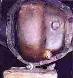
-
Apply light bead of gasket maker and install differential cover. I let gasket maker dry for 1 day before filling with oil. -
Remove tie rod end cotter pins and nuts., flip them over and install flat with end of tie rod threads. Hammer side of steering knuckle where tie rod mounts with hammer. If tie rod does not fall out, hammer nut reinstalled upside down on tie rod. Do not get crazy hitting top of tie rod, or you will damage tie rod and/or nut threads. 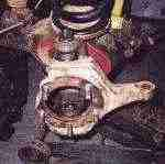
-
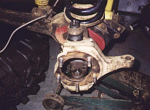
Remove upper and lower ball joints, cotter pins and nuts. Hit top of ball joint very hard and both ball joints and knuckle will drop down. Get ready to catch it or it will hit the floor. I had ball joints pressed in by machine shop. Alignment shim can be seen in upper ball joint hole. I did not replace/adjust alignment shims. These do not wear out and should not be messed with unless your alignment is off. I recommend leaving these alone until new ball joints and other front end parts are installed. Bad ball joints can cause havoc on alignment. Replacement of ball joints may actually re-align your front end for you. 
-
Install knuckle and ball joints, torque to specification. Install tie rod ends, torque to specification. Install cotter pins in upper ball joints and tie rod ends. -
Inspect axle shaft u-joints and seals. SPICER solid, non-greasable u-joints are supposed to be the strongest. Marine grease is installed to supposedly keep out water. I am installing these now and will update later on how they work. The two seals on outer part of each axle shaft are part of SPICER kit # 706527-x (this kit contains small needle bearing, needle bearing grease seal, and both axle shaft dust shields). 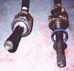
-
Reinstall axles. Be very careful when shaft is almost in. Grease seals you replaced inside axle tubes can be damaged easily. Support axle shaft so that the inside end stays in the center of axle tube. Oil can be applied to end of shaft to facilitate entry (sounds kinky)!! -
Inspect needle bearing seal and small internal needle bearing for wear. This seal and bearing are part of above mentioned SPICER seal kit. Seal comes right out, but needle bearing will have to be pried out with screw driver. It will be necessary to destroy bearing to get it out. 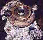
-
Install axle flanges and caliper brackets on knuckles. Torque the 5 nuts to specification. -
Grease bearings, install inner bearing and install grease seal. Grease seal can be lightly tapped in with hammer. I use marine/4wd grease. Some marine grease is made from a different base than most greases and can not be mixed. If you use this grease, make sure all old grease is removed from all bearings/surfaces. -
Install rotor/hub. Install outer bearing. Install inner bearing nut. Torque to 50 ft.-lbs. And back off 1/4 turn. Re-tighten nut by hand only. The inner bearing nut may have a small pin that fits into small ring with holes. This pin must face outward. Install ring with holes, ensuring groove in axle flange lines up with tab on ring and that pin on inner bearing nut lines up with one of the holes in ring. Inner bearing hub nut may have to be adjusted slightly to accomplish this. Install outer bearing nut (locknut) and torque to specification. -
Install spring and inner/outer hub locking mechanisms. Ensure these are clean from gunk and rust. Also ensure that they are heavily greased. I use marine/4wd grease for these assemblies. Install snap ring on end of axle, axle shaft may again have to be pushed from back as in step 5. Install flat steel round plate (if equipped) and large spring clip. -
Inspect hub O-ring seals. One is around outer hub, one is in between plastic center and metal part of hub. Outer seal must be bought in packs of 8 from FORD. Replace hub and tighten allen bolts to spec. -
Install caliper. Grease contact points between caliper and bracket. Hammer in caliper shims, making note of orientation. Apply Never-Seize on caliper bolt. -
Ensure hubs lock/unlock easily and rotors rotate fairly easy. Install tires and torque to specification. -
If oil comes out of axle tube after installation is complete, it may be residual oil left in tube. Give it a couple days and see what happens.


|
Off-Road.com Newsletter Join our Weekly Newsletter to get the latest off-road news, reviews, events, and alerts! |
Follow @Off-Road
 Your Privacy Choices