The 80 Pro XT, like its cousin the 80 Series, are full sized off-road lights
designed for extreme racing conditions. PIAA Corporation of North America
provided Off-Road.com with a pair of these in a Driving pattern for the HUMMER
project vehicle. Please send questions and comments on the review using the Feedback
button at the bottom of this page or by using the address above.
 |
Touted features from the 1997 Catalog:
|
Contents
- Product Tested
- Component Evaluation
- Installation
- Performance
- Summary
- Related Products
- Related Links
Product Tested
We elected to test the 80 Pro XT in a Driving pattern. A driving pattern gives good distance illumination while still working up close, and according to PIAA, is the most popular pattern. Other patterns include a Fog and Pencil beam, all with clear lenses. All share the same housing with only the lens/reflector assembly differing. These assemblies are available separately, allowing one type to be converted to another.
Note that these lights are for off-road use only. They are too powerful for on-road use no matter what pattern is selected.
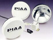
We ordered Part #8362, which is the Driving Pattern Kit which includes 2 Lamps, PIAA Quartz Halogen Bulbs, Lamp Covers, and the Pre-assembled Wiring System. In addition to the kit, customers can order Single Lamps, Replacement Bulbs, Replacement Lens/Reflectors, Pre-assembled Harnesses, and Covers individually.
The kit comes in a nice display box showing off the lenses with everything
neatly packed in styrofoam. Even some nifty stickers were thrown in too. My only
gripe is that the wiring instructions (in fact all instructions) are printed on
the box instead of on a separate piece of paper. The black text on the
reflective silver box is a little difficult to read. Plus, it is terribly
inconvenient to drag around while trying to do the install.
Evaluation - Lamp Assembly
Each lamp consists of a die cast aluminum housing with a black powder coat. Aluminum, of course, is good because of its low weight, strength, corrosion resistance, and thermal conductivity. From a manufacturing standpoint, the raw materiel costs more and the machining is more expensive. This is the first example of the excellent PIAA engineering and the quality of lights they produce.
The mounting system is also very clever. The post assembly nestles between two ears on the housing with a pin passing through the 3 pieces. This allows the lamp to be mounted on anything from a vertical surface to a surface 30 degrees past horizontal! Furthermore, the actual threaded post slides in a locking channel assembly allowing the light to tilt 15 degrees either way. The post assembly is made of die cast zinc. Zinc is softer than steel allowing the bracket to have an very good grip to the mating surface. Zinc also absorbs some of the vibration passing through the mount and is corrosion resistant.
The lens is made of heavy duty, optical quality leaded glass. The lens is tempered 4 times to add strength and further improve resistance to flying debris. The reflector is made of steel and is both zinc plated and aluminumized to prevent corrosion. The lens and reflector are sealed together to form a single piece using a heat resistant silicone. There is a small vent hole at the bottom interface. The bulb attaches via a locking spring clip assembly. The lens/reflector assembly attaches to the housing via a screw on each side. There is a neoprene gasket around the rim to ensure a dust and moisture free seal.
The wires also enter the housing through a gasket, hence, the entire lamp is pretty much sealed up. The vent in the lens is required to allow the light to "breathe" and vent out moisture during operation. Heat is transferred from the reflector and lens to be dissipated through the housing and cooling ribs. The wires are sheathed in a heat resistant fabric where they near the reflector and bulb, a nice touch.
Each light uses a 120W H3 bulb. The actual bulb is make of quartz to withstand the heat. The PIAA bulb is one of the most powerful and can continue to function after long periods of use under harsh conditions. Everyone that I talked to that use this bulb have been very pleased with the overall life and consistent light output. There is no upgrade bulb available.
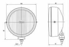
The lamp is 7" tall from the mounting surface to the top of the housing. It is 6 5/8" wide with the lens being about 6.5". As shown in the figure, the mounting post is just about even with the rear of the housing. The lamp is a mere 3" deep.
The kit includes two plastic slip over covers to protect the lenses when not in use. They are white with a black PIAA logo and slogan. The fit tightly but are still easy to remove. I feel that the colors should be inverted: a black cover with white letters.
Evaluation - Wiring Harness Assembly
One of the key benefits of PIAA kits is the pre-assembled wiring harnesses, usually precluding the use of wire cutters, crimp connectors, or solder. They even provide wire tie wraps (zip ties) for a finished appearance.
I was very impressed at the quality of the harness. Most wiring is in black split loom or plastic tubing to protect the wires' insulation. Ring terminals are crimped to the wire, soldered, and then covered with heat shrink (for the positive leads). Quick connect, locking connectors come pre-assembled at key places. Please see the figure in the Wiring section for wire lengths and hook up information.
The lamp control circuit is pretty standard. A low current (illuminated) switch is used to activate a single relay. The current then flows from the battery, though a 30A fuse, then the relay, and off to the lights.
The single relay and 30A fuse are housed in a dust and moisture resistant housing with a metal mounting flange. The fuse is an ATC (blade type) mounted on a PC board with the relay for a clean durable assembly. The box is just about 3" on a side with the bracket sticking up another 1/2".
The switch is an oval push button style with an illuminated ring. The ring glows red when the light is on and green when the light is off but ready. The button is integrated into a mounting bracket, and the assembly measures about 2" wide, 1" tall, and 1/2" deep.
|
We bench tested the harness using a single lamp only using a Lambda current and voltage limiting linear power supply. With 13.8 V at the input terminals, we measured 13.5V at the light and 7.15A. A 0.3V (2%) drop is quite good actually for a factory wiring harness. We expect the drop to increase to 0.4V (3%) with 2 lights due to shared wiring. As indicated in the figure, the common power wire is 12 gauge, switching to 14 gauge (along with the ground wire) for the individual light connections.
Installation - Lamps
The hardest part is selecting a good spot for the lights. There are differing beliefs on whether they should be high (roof) or low (bumper). The high mounting gives better distance illumination but the lights have to be aimed down at some point. Hood reflection is a problem on some vehicles. With the lower mounting, the vehicle drives along the light path, but the light also is obstructed easily.
Once a location is selected, only one hole is required for the post. Since the 80 Pro has the channel locking feature to allow tilting, the base of the lamp is wider than a normal post. Ideally the full 2.5" width should be supported but is not critical. The wide base allows a firmer mount.
No aiming instructions are provided with the lamp, quite an oversight if you ask me. So we applied some general mounting guidelines assuming a bumper/brushguard mounting. Left to right depends on the lighting you require. Ideally the left and right patterns should overlap in the center for a continuous illuminated area. A simple method is to ensure that the lamps are parallel to the front of the vehicle, i.e. pointed straight ahead. For Driving lights, the center of the hot spot should be at a height equal to the mounting height when projected on a wall. In other words, the lamps are perpendicular to the ground. They can be aimed down slightly to improve the up close lighting.
Installation - Wiring
As mentioned before, PIAA provides instructions on the box but not in paper form. While the supplied instructions are sufficiently clear and detailed enough to do the install, we have provided a more detailed set of wiring instructions in the hope of not only helping an 80 Pro install, but as an example for just about any lighting product.
It might be wise to mount the lights first. Then, start laying out the wiring starting with the lamps and working back. Hence, we can better ensure where the relay box will be located. The switch wires are quite long so that is not a problem usually.
This figure shows all the major components in blue. The black number are the lengths of wire included in the PIAA harness. The numbers in red are connections that need to be made and are detailed as follows.
|

- Switch Ground - black. The ring terminal needs to be connected to ground. Since the switch is lighted, this wire provides the ground for the dual-color LEDs. If this wire is not hooked up, the lamps will function correctly but the switch ring will not illuminate.
- Switch Positive - white/black trace. This wire actually has two functions. First, it supplies 12V power to the switch illumination LEDs. Second, it supplies the relay control circuit with 12V to turn the lamps on. This wire should be connected to a source that is hot when the 80 Pros can be enabled. When this wire is hot, the switch ring glows green with the 80's off, and red when on (assuming that the ground is attached [1]). See below for wiring ideas.
- Relay Control Positive - white. This wire connects via a bullet connector to the relay box. When the switch is on (closed), the Switch Positive [2] is passed through to this wire. It provides the 12V to the relay control coil.
- Relay Control Ground - black. The ring terminal attaches to a grounded stud and supplies the ground for the relay control coil. This combined with the positive input [3] forms the low current circuit to enable the 80 Pros.
- Relay Positive Input - white. The ring terminal is to be attached directly to positive battery terminal or other good source of high current 12V. When the relay is closed, current flows down this wire, through the relay, and to the lamps via the Lamp Positive [7] wires.
- Lamp Ground - black. The ring terminal must be attached to a good high current ground. These wires are the path to ground for the lamps.
- Lamp Positive - white. No connections need to be made by the installer. This common wire splits and goes to each of the 80 Pro lamps, providing the positive path via the relay and Relay Positive Input [5].
The only tricky part is that the switch controls the positive feed [3] to the relay control circuit while the ground is constant [4]. The Switch Positive wire [2] supplies the 12V to the switch. As indicated above, this needs to be connected to a controlling source. The instructions are a little vague on this point. The wire could be attached to the parking lamp circuit. The 80 Pros could then be turned on only when the parking lights (or headlights) are on. The switch ring would glow green or red depending if the PIAA switch was off or on. It could also be attached to the headlight circuit to allow the lights to be on only when the headlights are on. For a really useful install, connect the wire to the high beam circuit. If the PIAA switch was left on, the factory high beam switch would turn on the 80 Pros along with the high beams. Note that this should be used off-road only.
Performance
There is no substitute for good lens (and fluting) and large surface area reflectors for directing the light. We commented on the high quality PIAA lens above. Since the majority of the light comes from being bounced off the reflector, the more area, the better the control. Hence, given equal quality, lamps with larger reflectors will have better performing patterns, especially with higher wattages.
The 80 Pro XT does not disappoint.
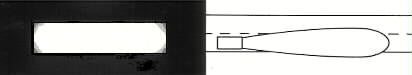
The light pattern is extremely sharp, forming a near perfect rectangle instead of the more common oval shape. The pattern measures about 6 degrees vertical and 22 degrees horizontal. This is about 1' vertical and 4' horizontal at 10' away. The extreme beam control comes from the prism cut lens and non-parabolic reflector, meaning that light is not wasted shining on the stars. However, the Driving pattern is definitely better for medium to long range illumination. The strong horizontal cut-off does not provide much light down in front, up close.
The figure above shows the pattern as projected on a vertical surface and an overhead view. There is an oval hot spot in the center, but the light is pretty even over the entire pattern, lessening at the corners only. Given the shallow reflector (and overall depth) of the 80 Pro, the extreme beam control is a tribute to the engineering staff.
Summary
The PIAA 80 Pro XT kit is excellent in every respect. From the tempered lenses to the locking channel mounts to the lighted switch, the components are of the highest quality. However, what makes the lamps truly exceptional is the way they are combined into a single product that exceeded our expectations. Nothing is left to be desired.
I like the illuminated ring on the button. It makes finding it in the dark much easier. It is easy to operate with a positive action. I do find the housing to be a little larger than it needs to be but this is a small gripe. The switch could be easily changed if so desired.
The lights are of the highest quality construction and should provide many years of excellent performance. If you are looking for a no compromise full sized light, the 80 Pro is the ticket. With the extremely thin depth, they should fit just about anywhere. We at Off-Road.com highly recommend these lights.
Related Products
The 80 Pro XT also come in Pencil and Fog Patterns in addition to the Driving pattern. The pencil is a tighter pattern with a horizontal spread of only 10 degrees (compared to 22 in the Driving) but with a vertical spread of 10 degrees (compared to 5 in the Driving). The pattern is also oval instead of a rectangle. The Pencil pattern is used for extreme distance illumination and is probably only useful for high speed racing use. The Fog pattern is wider than the Driving at about 40 degrees horizontal instead of 22 with the same vertical spread. This pattern is also very sharply controlled. "Fog" is a little misleading because these lights are too powerful for use in fog. Nevertheless, for off-roading, this pattern should provide a much wider area of illumination. However, they are still very sharply controlled to a rectangular pattern and might not be ideal for rock crawling though.
PIAA also makes the 80 Series lights with a dual beam H4 configuration. On the low setting, the pattern is lower and more full, providing better up close illumination. The high setting is brighter and more controlled for better distance. The 80 Series comes in Pencil, Driving, and Fog.
PIAA also sells light locks that will fit the 80 Pro XT. They are made my McGard and work just like a locking lug nut.
Related Links
We have several articles in the Tech section for further information about wiring:
Check out Off-Road.com's Product Showcase and Product Review sections for evaluations like this one.
PIAA is a registered trademark of PIAA Corporation.
Some images and content have been reproduced from PIAA literature with
permission of PIAA Corporation, USA. Further reproduction by any means is
prohibited.
|
Off-Road.com Newsletter Join our Weekly Newsletter to get the latest off-road news, reviews, events, and alerts! |
Follow @Off-Road
Buyers Guides
Visit Forums TRUCKS & 4x4 FORUMS
Copyright
VerticalScope Inc.

 Your Privacy Choices