After the purchase of my new 2000
Silverado 1500 Z71, I started the usual planning of the additions
such as a winch, auxiliary lighting, and much more. I did a little
research before running out to purchase these juice hungry
accessories. I felt it would be wiser to upgrade my electrical
system first, so I jumped at the opportunity from Wrangler NW Power
Products, INC. to install their dual battery tray, relay cable kit,
battery manager switch and harness, and an Optima 800U spiral cell
battery.

The Battery Manager Cable must be passed through the firewall into the passenger compartment. This is accomplished by carefully locating an area to drill the needed ½" hole. I chose an area just to the right of the brake booster that had a dimple. I drilled a 1/8" pilot hole to ensure of the holes' location in the engine compartment. The dimple was the perfect location. (The dimple may be a manufacturer defect in my truck though) On the inside I located that dimple under a plastic removable plug (Remove this plug).
Feed the battery manager harness plug through the hole from the engine compartment side extending it to the switch location. Work the grommet into the hole from the engine side and route the engine side of the battery manager cable along with the AUX battery POS cable to the isolation relay at the auxiliary battery tray.
I suggest you run the BM cable inside of the AUX battery cables' protective sheathing and use the small zip strips to secure it inside of the sheathing. Connect the Battery manager Harness to isolation relay as per Battery Manager Instructions/wiring diagram.
I WAS IMPRESSED BY THE EASE OF INSTALLATION AND THE PRODUCTS QUALITY. The lugs are all sealed and strengthened with heat shrink tubing. The cables are made from 2 guage super flexible fine strand hi-amp copper. I would highly recommend any of Wrangler NW Power Products, INC. products. The customer service is second to none and they will stand behind their products.
My new 2000 Chevrolet pickup came equipped with a 5.3L Vortec engine and fortunately has a 130-amp alternator. A lot of upgrades required more upgrades and changes ending up costing you an arm and a leg. The new Optima 800U along with the dual battery kit will work fine with my existing battery and electrical system. Steve Schroder at Wrangler NW suggested the following items to facilitate my needs:
| DESCRIPTION | PART NUMBER |
| TRAY KIT,AUX BAT,SILV,SERA,99-00 | 34-959-5 |
| RELAY/CABLE KIT,99-00, CHEVROLET | 34-959-5R |
| BATT MGR SW/HR,99-00, SLVRADO, SIERRA | 34-959BM-5 |
| BATT,12V,PP800 | 18-800U |

Click picture for larger image |
|
|
Auxiliary Battery Tray |
Relay and Cable Kit |


Click picture for larger image |
|
|
Battery Manager Switch and Harness |
Optima 800U |

Follow along as we install a Dual Battery Tray, Relay/Cable Kit, Battery Manager Kit, and an Optima 800U battery in my truck. Please read the following warning prior to the installation of these items: WARNING: Please remember that you will be working with highly explosive batteries. Therefore, be very careful and please wear eye protective gear and remove all jewelry, to include rings, bracelets, and necklaces.
|
|
|
This kit will work on all 2000 Chevrolet Silverado Pick-ups, Tahoes, Suburbans and all 2000 GMC Sierra Pick-ups, Yukons, and Suburbans with gas engines. |


Click picture for larger image |
|
|
The first step is to remove the upper fender support bracket between the right side (passenger side) fender and firewall using a 13mm socket. This bracket and 4 bolts will no longer be used, but I recommend that you keep them in case you trade or sell your vehicle and keep the dual battery kit for your next truck. |
Next is to remove the radiator overflow tank assembly and move it out of the way for removal of lower fender support bracket. You will need a deep-well 10mm socket and wrench to remove the 1 nut and 1 bolt. The tank hooks on the fender also. |


Click picture for larger image |
|
|
The lower fender support bracket between the right side fender and firewall (four 13mm nuts requiring a deep-well socket) that is attached to the inner fender well with one 10mm bolt is next to be removed. The bracket will not be reused, but keep the nuts and bolt to secure the new battery tray assembly into the same place the lower fender support came from. (Again I recommend holding onto the lower bracket) |
Before installing your new battery tray, install the 200-amp continuous duty relay to the inside of the new battery tray (11mm wrench is needed), also install the small ground wire from the relay (COIL NEG) stud to relay mounting bolt on the battery tray. All wires are clearly marked with the location of each connection. The relay and its ground may have been installed prior to shipping. |

Note: Wrangler NW uses a 200-amp continuous duty relay. This is a heavy-duty relay with silver alloy points that will not stick or corrode.
|
|
At this time you are ready to install the new battery tray with relay into the position where the lower fender brace was removed, using the existing threaded studs at the firewall. You will use the existing 4-13mm nuts and 1-10mm bolt that were holding on the lower fender support to mount the new battery tray. Tighten all nuts and the bolt securely. Reinstall the radiator overflow tank, tightening those mounting nut and bolt. BE CAREFUL NOT TO OVER-TIGHTEN THE BOLT AND NUT, THE COOLANT RESERVOIR IS PLASTIC AND WILL CRACK EASILY. |

Next we needed to get out the cable kit. The cables are labeled NEG and POS and cut to length. The lugs are all sealed and strengthened with heat shrink tubing. The cables are made from 2 guage super flexible fine strand hi-amp copper.
Route the long Positive Battery Cable between the Main Battery terminal and the 200-amp continuous duty isolation relay. Ensure you route the cable to the rear of the engine compartment close to the firewall and away from any hot surfaces that may melt or damage the cable and/or protective sheathing. This cable should be zip tied to the existing wiring loom that runs along the firewall in the rear of the engine compartment. (WAIT TO ZIP TIE ANYTHING UNTIL THE END) Install the cable end at the relay using a 13mm wrench. (SEE WIRING DIAGRAM FOR PROPER CONNECTION) DO NOT INSTALL THE BATTERY CABLE TO MAIN BATTERY AT THIS TIME!
  Click picture for larger image
|
|
Loosen the nut for the battery hold down on the auxiliary battery tray. Mount the new OPTIMA Red Top 800U Battery by ensuring the side terminals are pointed to the inside, tilt the corner down and set the battery on the tray flat. The outer side of the tray has hooks to secure the edge of the battery and the inner side of the tray has the hold down. Once the battery is in place, secure it with the hold down bracket. Also three military connectors came with the relay kit. At this time take off the plastic plugs on the side terminals of the AUX Battery. Use the two shorter/single military connectors and screw them into the POS and NEG side terminals of the AUX Battery. |
OPTIMA is the most advanced engine starting battery
available today. Their patented SPIRALCELL Technology provides many
features and benefits not found in conventional automotive
batteries: The Optima's SPIRALCELL Technology provides more power
for faster, crisper starts. The 800U 12-volt model delivers 800CCA
at 0°F.
OPTIMA provides high output power faster and longer than
conventional batteries, resulting in greater cranking ability and
less capacity reduction at high current loads.
OPTIMA batteries fully recharge in as little as one hour - more
than twice as fast as other batteries.
OPTIMA won't spill, leak, or corrode; it's the safest, cleanest
battery on the market. The OPTIMA can be mounted in any position -
sideways, or even upside down.
OPTIMA lasts up to two years longer than conventional batteries
providing years of reliable, convenient performance and exceptional
value. Our high purity lead design provides a much longer shelf
life, meaning the OPTIMA can sit unused for up to one year and
still start your equipment.

Click picture for larger image |
|
|
Install the auxiliary battery positive cable to the POS terminal of the auxiliary battery and the other end to the auxiliary side of the isolation relay. |
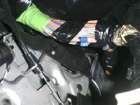
The auxiliary battery ground cable is installed between the AUX negative battery terminal and engine block ground. The picture shows the engine end of the connection from below. I used the bolt that holds on the dipstick tube to secure the AUX battery ground cable. |

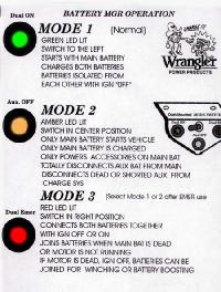
The next part is the installation of the BATTERY
MANAGER SWITCH. This is an exceptional way of managing the dual
battery set-up. Below is a picture of the operation of the Battery
Manager Switch, which will show you the functionality of this
system.

The battery manager system comes with a pre-wired harness with all wires labeled for very easy hook up. The kit even included wire ties for tying your harness back and numerous types power taps for connecting to a power source under the dash. Find a location under the dash of the vehicle for the battery manager switch.
The most preferable location is a comfortable distance in front of the driver. Ensure that the switch won't be bumped when entering and exiting the vehicle. I Opted to install the BM switch just to the right side of the steering wheel at the lowest point of the dash panel along the metal portion running along the bottom edge of the dash. Hold the switch in place and mark the screw holes with a small tipped marker and then use a 7/64th drill bit to drill out the holes. Using a ¼" nut driver, secure the switch to the dash with the two screws furnished in the battery manager switch and harness. The switch is mounted very firmly when you use the metal lip to attach it to the dash.
|
|
|
The switch is mounted under the dash. |

The Battery Manager Cable must be passed through the firewall into the passenger compartment. This is accomplished by carefully locating an area to drill the needed ½" hole. I chose an area just to the right of the brake booster that had a dimple. I drilled a 1/8" pilot hole to ensure of the holes' location in the engine compartment. The dimple was the perfect location. (The dimple may be a manufacturer defect in my truck though) On the inside I located that dimple under a plastic removable plug (Remove this plug).
|
|
You'll need to remove the cover from the aux fuse/relay box (located left of the brake pedal) then there are clips to release it and move it out of your way enough to drill the hole from the inside. |

 
Click picture for larger image
|
|
Drill the ½" hole through the firewall from the inside and clean off all burs. |
Feed the battery manager harness plug through the hole from the engine compartment side extending it to the switch location. Work the grommet into the hole from the engine side and route the engine side of the battery manager cable along with the AUX battery POS cable to the isolation relay at the auxiliary battery tray.
I suggest you run the BM cable inside of the AUX battery cables' protective sheathing and use the small zip strips to secure it inside of the sheathing. Connect the Battery manager Harness to isolation relay as per Battery Manager Instructions/wiring diagram.
|
|
Here is a basic wiring diagram that comes with the battery manager kit. This made everything easier when it came to connecting the wires. Also on this sheet (but not shown here) are other diagrams showing the different ways to tap into a power source with the multiple connectors that are sent with the kit. The instructions are easy to follow, but just in case you have a problem or you think your kit is missing something you can call Wrangler NWs' TECH LINE @ (503) 235-4110. The Tech Line is available Monday thru Friday, 7:30 A.M. to 4:30 P.M.PST. |

Now it is time to find a power source for your Battery Manager
system. There are numerous ways to go about doing this. Wrangler
NW's kit comes with multiple ways to do this through Fuse Taps,
Add-A- Circuit Fuse holders, Piggy-back IGN circuit Power Taps,
Power-T-Taps, ect… They ensure that whatever type vehicle
you own or how the owner wants to source the power for the battery
manager that the needed Taps are provided.
The instructions that came with my kit suggested that I use a fuse Tap and source the power from the fuse center on the drivers' end of the dash. This can be done by locating the IGN 3 fuse, installing the fuse tap and connecting to the fused pigtail from the battery manager switch. ENSURE THAT THIS FUSE HAS VOLTAGE WITH THE IGNITION SWITCH IN THE RUN POSITION ONLY. I Opted to source my power from a wiring loom coming from the backside of the fuse center and use the "T" Tap. Using a test light, I clipped on a good ground, turned my ignition switch onto the run position and started hunting for my power source. The first wire I chose was a larger pink wire and it was "HOT". I now had to test this wire to make sure that it had VOLTAGE WITH THE IGNITION SWITCH IN THE "RUN" POSITION ONLY, NOT IN "ACCESSORY" OR "START" positions. I probed through the wire with my test light and ensured the ground was getting good contact and then went through each position of the ignition switch. The pink wire worked perfectly, so I used the "T" Tap provided in the kit to tap into the pink wire.

 
Click picture for larger image
|
|
After tapping the pink wire you have to cut the end from the fused pigtail, strip off the end of the wire and crimp the "Large Quick On Insulated Male Terminal" P/N 32-AA2261.Connect the new end to the "T" Tap on the pink wire and then connect the opposite end to the BM harness as shown in these photos. |
 You can attach the Auxiliary Battery
Positive Cable to the main battery positive terminal using the
double military connector included in the kit. Remember that when
you disconnect the main battery you will lose all radio memory so
write down those presets to be on the safe side. Disconnect the
negative and positive terminals. I only used half of the double
connector to connect the AUX BAT POS Cable.
You can attach the Auxiliary Battery
Positive Cable to the main battery positive terminal using the
double military connector included in the kit. Remember that when
you disconnect the main battery you will lose all radio memory so
write down those presets to be on the safe side. Disconnect the
negative and positive terminals. I only used half of the double
connector to connect the AUX BAT POS Cable.
Using the base of the double connector I put it through the AUX BAT POS cable and tightened it down to the main battery. Next I put a brass washer on the Main Battery POS cable stud and screwed it into the end of the double military connector I just secured the AUX POS BAT cable with. Make sure to put the plastic safety cap back on the Main Battery POS cable and then connect the Main Battery Negative cable. Go back and make sure that all nuts, bolts, and connections are tight.
Before tucking, securing and zip tying the wires, I recommend that you test out the system to ensure everything is hooked up the correct way. Put the Battery manager Switch in the "Dual On" position, turn the ignition switch to the "RUN" position and you can test the relay operation by removing the POS cable from the AUX battery, attach a volt meter to the detached cable, turn on the ignition switch and the meter should read battery voltage at 12 to 12.5 volts, turn the switch off and the voltage reading should be zero volts.
Another easier way to test this is to keep the
Battery manager Switch in the "Dual On" position (without
disconnecting the POS Cable), start your truck, (IGN switch in the
"RUN" position), attach a volt meter to the positive terminal of
the AUX BAT POS terminal and a ground, the meter should read
battery voltage at 14 to 14.5 volts, turn the battery Manager
Switch to the "Dual Off" position, shut the truck off, the voltage
reading should be 12 to 12.5 volts.
|
 
Click picture for larger image
|
|
The final step is to tuck all of the wires and harnesses away from all hot surfaces, pedals, and moving objects. The kit comes with more than enough zips ties to secure everything. After you have driven the vehicle for approximately 100 miles, check and re-tighten all hardware if needed. Here are a couple pictures of where I secured the wires and cables. |
I WAS IMPRESSED BY THE EASE OF INSTALLATION AND THE PRODUCTS QUALITY. The lugs are all sealed and strengthened with heat shrink tubing. The cables are made from 2 guage super flexible fine strand hi-amp copper. I would highly recommend any of Wrangler NW Power Products, INC. products. The customer service is second to none and they will stand behind their products.

Click picture for larger image |
|
The final look shows a very professional, well thought-out system that works well with my existing electrical system. The new Dual Battery System almost looks like it was a factory option. Here is a picture of the completed install. |
 4444 S.E. 27th Ave. Portland, OR 97202 USA 800-962-2616 Email: info@wranglernw.com www.wranglernw.com |
Questions or Comments about this
page should be directed to:
chevy@off-road.com.
chevy@off-road.com.
We cannot
guarantee a response to every letter we receive. Back to the Chevy
WebPages
|
Off-Road.com Newsletter Join our Weekly Newsletter to get the latest off-road news, reviews, events, and alerts! |
Follow @Off-Road
 Your Privacy Choices