 |
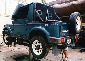
Our spring over axle conversion begins. Off-Road.com's project Samurai goes up on the lift at Petroworks Off-Road Products in Fallbrook, CA. |
Parts and equipment required
|
|
Preparation
 Essentially the entire
suspension and both axles need to be removed. The only thing that
can stay attached is each of the springs (by one end, anyway). The
vehicle will need to be raised to a significant height to clear the
various components to be removed and supported by the frame. This
will be a much easier job to perform if you get a friend to help as
there are portions of the process that will be much easier with two
people (and perhaps should be done with two people) like wrestling
the axles out and onto a suitable work surface.
Essentially the entire
suspension and both axles need to be removed. The only thing that
can stay attached is each of the springs (by one end, anyway). The
vehicle will need to be raised to a significant height to clear the
various components to be removed and supported by the frame. This
will be a much easier job to perform if you get a friend to help as
there are portions of the process that will be much easier with two
people (and perhaps should be done with two people) like wrestling
the axles out and onto a suitable work surface.
For safety:
- Disconnect the battery negative cable.
- Raise and properly support the vehicle.
You'll also need to:
- Release the emergency brake.
- Set the transmission and transfer case to neutral.
How you go about doing this conversion will depend on whether or not you have access to a hydraulic lift, and whether or not you'll be doing the welding where you are doing the rest of the work. Obviously, if you have to take the axles out somewhere to be welded, this is gonna be a bit more complex than if you can weld ‘em where you drop ‘em. In my case, the hydraulic lift and the welding were in the same place as the vehicle, but I know that's a luxury most people won't have. While my situation certainly made things easier to do, it doesn't preclude you doing this in the garage or driveway.
Disassembly
Remove all four wheels.
Remove all four shocks.
Remove the front and rear flexible brake lines.
Remove brake line clips from the flexible brake line connectors.
Plug the rigid brake lines where they’re open under the vehicle.
Disconnect and remove the emergency brake cable from each rear wheel.
Remove the front and rear propellor shafts.
Drain the front and rear differentials.
Remove the stabilizer and stabilizer brackets.
Remove the steering damper.
Separate the pitman arm from the drag link.
 Remove the nut and washer from the steering box shaft.
Using a puller, remove the Pitman arm from the steering box shaft.
Note: It is not necessary to disassemble the axles themselves.
 |
Pick an axle to start with and make sure it is well supported. Supports should be placed just inboard of the springs. |
| Front Axle | Rear Axle |
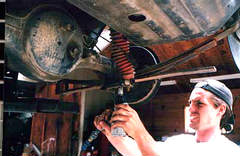
| Double-check to make sure the axle is well supported. Remove the spring seats from the bottom of each spring on the selected axle by removing the u-bolt nuts. An impact wrench comes in really handy here. | |
| Remove the lower shackle pins from the front of each front spring. It is not necessary to remove the upper shackle pins nor the spring bolts from the rear of each spring. | Remove the lower shackle pins from the rear of each rear spring. It is not necessary to remove the upper shackle pins nor the spring bolts from the front of each spring. |
 Remove the inner shackle plate from the shackle. Rock each spring
down clear of the axle. Using two people, remove the axle from
under the vehicle. Remove the rigid metal brake lines from the
axle.
Remove the inner shackle plate from the shackle. Rock each spring
down clear of the axle. Using two people, remove the axle from
under the vehicle. Remove the rigid metal brake lines from the
axle. |
|
Welding
 Place the axle on a suitable surface, with the existing spring pads
pointed exactly down and with the mounting surface level,
and grind clean the area immediately opposite the existing spring
saddle pads.
Place the axle on a suitable surface, with the existing spring pads
pointed exactly down and with the mounting surface level,
and grind clean the area immediately opposite the existing spring
saddle pads.
Position the new spring saddle pads, making sure that they are square and the top surface is level.
 Weld the new pads in place by first tacking them in position, then
welding a portion at a time to avoid damaging or warping the axle
tube. See the drawing on the right. Take your time, work carefully,
and allow the axle tube to cool between welds.
Weld the new pads in place by first tacking them in position, then
welding a portion at a time to avoid damaging or warping the axle
tube. See the drawing on the right. Take your time, work carefully,
and allow the axle tube to cool between welds.
While the front axle is cooling, cut or grind the old front lower shock mounts from the spring seats. Weld the new front lower shock mounts to each front spring seat, taking care to remember the orientation that the new seats will assume when reinstalled. (The new rear lower shock mounts will be installed by welding them in place after the rear axle has been remounted).
When the axle tube has completely cooled, repaint ground areas, fresh welds, and bare metal on the axle tube and spring saddle pads.
Other modifications
 |
Clamp each spring next to the spring locating pin, and remove the pin. |
 |
Invert the pin, reinstall it and tighten securely. Remove the clamp on each spring. |
 Swing the spring back to its normal position in the shackle.
Reinstall the shackle pins, being sure to orient them with the nut
towards the body centerline. Torque each shackle pin to 22.0-39.5
ft-lb. (3.0-5.5 kg-m).
Swing the spring back to its normal position in the shackle.
Reinstall the shackle pins, being sure to orient them with the nut
towards the body centerline. Torque each shackle pin to 22.0-39.5
ft-lb. (3.0-5.5 kg-m).
Install the emergency brake cable drop bracket.
Install the rear shock upper mounting bar.
Install the new rear bump-stop brackets.
Install the new rear bump stops.
 Hammer over
the perpendicular welded seam on the inside of the rear of the
front fender, to prevent any rubbing with larger tires. Use a
ball-peen hammer. If you work slowly and don’t use heavy
blows, the seam should bend over without popping the welds.
Hammer over
the perpendicular welded seam on the inside of the rear of the
front fender, to prevent any rubbing with larger tires. Use a
ball-peen hammer. If you work slowly and don’t use heavy
blows, the seam should bend over without popping the welds.
While you’ve got the axles out on the ground, you may as well install that locker you’ve had your eye on. It's certainly easier to do it now than have to crawl under it later. I installed a Detroit EZ locker in the rear.
If possible, get the ol’ Mark I “flame wrench” out and put a pair of bends in your drag link to cause it to run parallel again. See Larry Harris’ article on this.
Reassembly
Once again, pick an axle with which to start and make sure it is well supported once it has been lifted into place just below the springs. Supports should be placed just inboard of the springs.
Note: All torque specs are from the Suzuki manual for the 86-87 Model years (which also covers “early ’88s”). Be sure to check the torque specs for your year Samurai, and follow manufacturer’s recommendations for the reinstallation and proper torque for each fastener. If you break a fastener, be sure to replace it with only the same grade fastener!
| Front Axle | Rear Axle |
 Double-check to make sure the axle is well
supported. Replace the spring seats on the top of
each spring on the selected axle.
Have a helper lift one end of the axle into position while you
place a u-bolt up from the bottom of the axle through the spring
seat and thread a washer and nut well onto each end of the bolt.
Lift the other end of the axle into position and fasten with
another u-bolt, washers, and nuts
Double-check to make sure the axle is well
supported. Replace the spring seats on the top of
each spring on the selected axle.
Have a helper lift one end of the axle into position while you
place a u-bolt up from the bottom of the axle through the spring
seat and thread a washer and nut well onto each end of the bolt.
Lift the other end of the axle into position and fasten with
another u-bolt, washers, and nuts
 Place the
second u-bolt, washers and nuts on each end of the axle.Tighten
each u-bolt ensuring that the locating pin on each spring enters
the hole on the new spring saddle pad. Once properly located,
tighten each u-bolt securely, drawing each end of the bolt down
evenly. Torque to 43.5-57.5 ft-lb. (6.0-8.0 kg-m). Place the
second u-bolt, washers and nuts on each end of the axle.Tighten
each u-bolt ensuring that the locating pin on each spring enters
the hole on the new spring saddle pad. Once properly located,
tighten each u-bolt securely, drawing each end of the bolt down
evenly. Torque to 43.5-57.5 ft-lb. (6.0-8.0 kg-m). |
|
| For the rear axle, slip the new rear shocks onto the upper mounting posts and slip the new rear lower shock mounts into the eye of each shock. Now rotate the shocks into place to find the new mounting position of the new rear lower shock mounts. Once you’ve marked the position of the new lower mounts, grind the axle clean in that spot, slip the shocks back off, and weld the new mounts into place. Once the axle has cooled, paint the bare metal, shock mounts and fresh welds. | |
Install the new dropped Pitman arm on the steering box shaft and reconnect the drag link.
Replace the washer and nut on the steering box shaft and tighten securely.
Reinstall the steering damper. The steering damper stay bolts (those that hold the formed sheet-metal piece to the Pitman arm) are torqued to 13.5-20.0 ft-lb. (1.8-2.8 kg-m). The steering damper nut (holds the bolt inserted thorough the stay and the damper eye) should be torqued to 25.5-39.5 ft-lb. (3.5-5.5 kg-m). The steering damper pin nut (fastens the opposite eye of the steering damper to the chassis-mounted pin) specs at 16.0-25.0 ft-lb. (2.2-3.5 kg-m).
Reinstall the front and rear propellor shafts. If you disassembled the shaft sections at the slip joints, be sure to align the match marks on the shaft sections, and install new boots if necessary. When re-installing the shafts, the driveshaft spacers will go in place at the front end of the front shaft, and the rear end of the rear shaft. Use the new longer bolts provided for the drive-shafts to fasten the spacers in place between the driveshaft flange and the differential flange on both propellor shafts. Torque all driveshaft fasteners to 17.0-21.5 ft-lb. (2.3-3.0 kg-m).
Refill the front and rear differentials using natural or synthetic SAE 80W-90, 75W-80 or 75W-90 hypoid gear oil (Suzuki “strongly recommends” the use of 75W-90 gear oil). Many of those who have expressed an opinion on this on the Suzuki mailing list have stated a definite preference for synthetics in the drive-train, citing better performance and quiter operation. Torque the filler plugs to 25.5-36.0 ft-lb. (3.5-5.0 kg-m). Drain plugs should be torqued to 29.0-50.5 ft-lb. (4.0-7.0 kg-m).
 Replace and reconnect the
emergency brake cable to the new dropped mount and each rear wheel.
Check to see if the cables will contact the new shock mounts or any
other portion of the axle assembly. If necessary, place a spacer
between the cable and the cable mounting points to move the cable
out clear of the new mounts.
Replace and reconnect the
emergency brake cable to the new dropped mount and each rear wheel.
Check to see if the cables will contact the new shock mounts or any
other portion of the axle assembly. If necessary, place a spacer
between the cable and the cable mounting points to move the cable
out clear of the new mounts.
Remove the plugs from the rigid brake lines where they’re open under the vehicle.
Replace the front and rear flexible brake lines with the new stainless steel braided brake lines, attaching them first to the rigid lines that are attached to the body and chassis of the vehicle, then to the brake cylinders at each wheel. Flare nuts are torqued to 10.5-13.0 ft-lb. (1.4-1.8 kg-m). The front brake line flexible hose bolts are tightened to 14.5-18.0 ft-lb. (2.0-2.5 kg-m).
Replace the brake line clips for the flexible brake line connectors.
Apply the Rancho shock decals, if desired, then install all four new shocks.
Replace all four wheels.
Lower the vehicle.
Warning: BLEED THE BRAKE SYSTEM! The Samurai uses a dual diagonal system, where the opposite front and rear wheels each use the same “main line”. For example, the left front and right rear brakes use the same line. Always bleed the wheel cylinder farthest from the master cylinder first (that is, do the rear wheels first). Be sure to keep the fluid reservoir on the master cylinder filled as you go along, and do a thorough job in bleeding the brakes.
Make sure to check all fasteners after you've put some miles on. The way Thorley recommends for headers isn't a bad idea here either:
- Check and torque to specs after one day
- Check and torque again after one week
- Check and torque again after one month
I'd check once a month thereafter as well, or after every off-road trip, whichever is more frequent.
--Scott Gomez
|
Off-Road.com Newsletter Join our Weekly Newsletter to get the latest off-road news, reviews, events, and alerts! |
Follow @Off-Road
 Your Privacy Choices