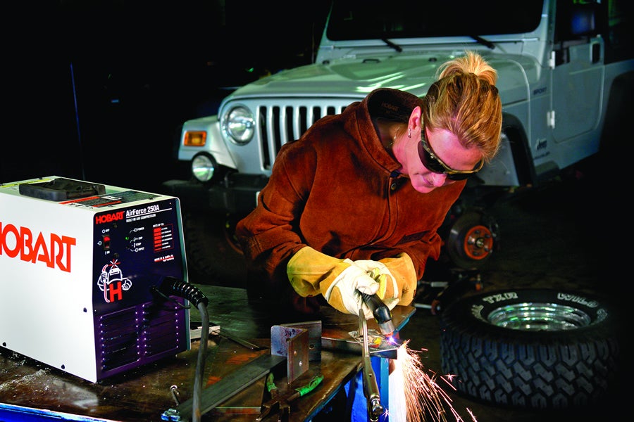
Weekend wheelers, rock crawlers and sand buggy fabricators who experience the benefits of a plasma cutting machine rarely want to return to oxy-acetylene cutting or mechanical cutting processes such as saws, cut-off wheels, shears and snips. Never again will they butcher a piece of sheet or tube to make a quick repair and with a recent decrease in the cost of ownership, a plasma cutter is a great tool to add to the garage and the envy of neighbors. Understanding the basics of plasma cutting is essential in selecting, operating and benefiting from a plasma cutter. Plasma 101 Plasma is the fourth and most highly energized state of matter: solid, liquid, gas and then plasma. In fact, plasma looks and behaves like a high-temperature gas, but with an important difference; it conducts electricity. The plasma arc results from electrically heating a gas (typically air) to a very high temperature. This ionizes its atoms and enables them to conduct electricity (If you’re reading this by a fluorescent light, you’re witnessing plasma in action!). A plasma arc torch spins a gas, typically air, around an electrode. The gas is heated in the chamber between the electrode and torch tip, ionizing the gas and creating plasma. This causes the plasma gas to greatly expand in volume and pressure. The small, narrow opening of the torch tip constricts the plasma and accelerates it toward the work piece at very high speeds (20,000 ft./s) and temperatures (up to 30,000 o F). The force of the high-intensity plasma jet pushes through the work piece and removes the molten metal. This jet easily cuts through metals with poor heat conductivity (stainless steel) or excellent conductivity (aluminum). The flame created by an oxy-fuel torch lacks plasma’s concentration and cuts stainless steel or aluminum so poorly (excess warping or dross) that professionals don’t bother to use it; they consider plasma arc cutting the standard process for these metals. Plasma cutting improves productivity and lowers the cost of cutting. It cuts faster, does not require a pre-heat cycle, minimizes the heat-affected zone and yields a cut with a small kerf (cut width). Plasma units also gouge, pierce, bevel, cut holes and trace shapes. In fact, the hardest part about plasma cutting is selecting a machine that best matches your application. How Big? Many people misjudge a plasma machine solely by amperage. While this is important, remember that total output power (in watts) equals amperage times voltage. This is one reason why the cutting capacity of a particular “size” plasma machine varies greatly by manufacturer (the other relates to standoff cutting, which will be discussed later). For instance, two models of 12-amp plasma cutters feature a built-in air compressor. However, Hobart’s AirForce 250A is rated at 110 VDC (1,320 watts total) while the other is rated at 70 VDC (840 watts total). The AirForce 250A provides 57 percent more cutting power and severs 1/4-in. steel. The second unit only cuts a maximum of 1/8-in. steel. Cutting Speeds and Quality Ratings Many manufacturers provide cutting speed charts that allow you to compare cutting speed performance. While there is no universal standard, Hobart facilitates an “apples-to-apples” comparison by qualifying capacity with three standards: rated cut, quality cut and sever cut. Rated cut is the thickest piece of metal that an operator can manually cut mild steel at a rate of 10 inches per minute (IPM.) This is considered the maximum speed at which an operator achieves a smooth, steady cut with the best possible cut appearance on the rated metal thickness. With a quality cut rating, the operator can cut thicker material, but at a slower rate. The edge of the cut is still smooth enough so the cut pieces can be welded together with little, if any, grinding. A sever cut rating means the operator is pushing the machine to its maximum. Cutting speeds will be very slow and the cut may require significant clean up. Fortunately, cutting speeds increase, as the material gets thinner. For example, the AirForce 400 cuts at 16 IPM on 3/8 in. steel, but reaches a cutting speed as high as 68 IPM on 1/16 in. steel! That is faster than mechanical or flame cutting units, and beats or matches all other plasma machines in its category. Primary Power Plasma cutting requires two basic elements, air and electricity, so the next question to ask when selecting a plasma cutter is what type of input power is available. If you only have 115V primary service, don’t worry. Several 12- and 27-amp plasma cutters, such as the Hobart AirForce 250A and Hobart AirForce 400, operate using 115 or 230 V power. The AirForce 250A and AirForce 400 can also maintain consistent current with input voltage variances up to 15 percent. This feature known as LVC (line voltage compensation) gives Hobart plasma cutters a significant competitive advantage. LVC enables the AirForce 250A and 400 to keep the output (cutting capability) constant regardless of minor fluctuations in input power that are found in rural settings, during times of peak-power consumption or when powered by a generator. Most competitive units only operate within a 10 percent voltage variance window, and they also tend to lose cutting current as the voltage level drops below the plasma cutter’s operating range. Don’t Trip Nuisance trips occur when a voltage drop creates an amperage spike, and long extension cords are notorious causes of voltage drops. The AirForce 400 is less susceptible to nuisance trips (voltage drops that create an amperage spike, often caused by long extension cords) because it draws 20 percent less current than similar, previous models. The AirForce 400 expands an operator’s work area by allowing you to use an extension cord up to 133 ft. on 230V/10 amp service or 53 ft. on 120V/20 amp service.
Air Supply Most manufacturers of hand-held plasma cutters recommend using ordinary air as the cutting gas. A small air compressor can meet this requirement. In mobile applications, contractors often opt for bottled nitrogen because it costs less than bottled air. When cutting stainless steel, some people believe nitrogen produces slightly less oxidation, but it’s not significantly different than air. For cutting thinner materials in the field, contractors involved with HVAC, sign making and maintenance often select a plasma cutter like the AirForce 250A because of its built-in air compressor. This lightweight package provides superior mobility. Remember - The air should be as clean and dry as possible to increase tip life and prevent down time. Most plasma cutters come with a built-in air filter but the addition of an in-line filter/dryer is suggested to further eliminate water, dirt and oil from the air. Standoff vs. Drag Cutting Drag cutting - just put the torch tip on the metal, pull the trigger and drag the torch. This lets you easily trace patterns or straight edges, as well as makes precision cuts with a minimal heat-affected zone. That means you won’t damage paint jobs or warp the metal – even when cutting stainless steel or aluminum (plasma cutting is NOT like oxy-fuel cutting). Standoff cutting - you manually hold the torch tip 1/16 to 1/8 in. off the metal surface. Standoff cutting improves the flow dynamics of the plasma jet, where drag cutting tends to disrupt the flow. For example, the AirForce 400 cuts 3/8-in. steel at 10 IPM when drag cutting and 16 IPM when standoff cutting. Using a standoff also increases maximum cutting capacity by 1/8 in. on this machine. Remember - When buying a unit with less than a 40 amp output, look for one with pilot arc control which gives you standoff cutting capability. Cutting Guides and Tips Different consumables and torch accessories enable configuring a plasma cutter for a variety of applications and operator skill levels. For beveling, cutting in corners and a better view of the cutting arc, some operators prefer an extended tip. This tip protrudes 1/2 to 1 in. beyond the retaining cup, enabling the operator to better direct the flow of the plasma jet and reach into corners. Having a steady hand is important because touching the tip to the work piece three or four times enlarges the hole to the point where it no longer constricts the arc sufficiently. If you do not have a steady hand ¾ remember that the cut will reflect any hand movement ¾ consider using roller guides (for straight lines) and circle cutting guides. These guides hold the torch in position so that it maintains consistent standoff height, prevents the tip from touching the work piece and makes it easier to travel in a straight line or cut a perfect circle. For easy beveling, roller and circle cutting guides permit independently adjusting wheel height to set the bevel angle. For removing old or imperfect welds, use a gouging tip. The hole on a gouging tip is three to four times wider than a regular tip. Its cone shape pushes out the plasma arc, which removes much more material than the constricted orifice of the regular tip.
Pre-Cut Checklist A few final words of advice before cutting: Follow proper safety procedures, wear personal safety equpiment and read the owner’s manual carefully! Inspect the torch tip, electrode and shield cup. Replace worn items. Check gas/air pressure at the compressor or bottle gauge. Turn on the plasma machine. Set the amperage control (generally to maximum) and check the air pressure. Grind off rust or paint where you plan to secure the ground clamp. This step is critical with 12-amp machines; they just don’t have the power to drive through rust and paint like larger units do. Place the ground clamp as close to the cut as possible, and place the clamp on the work piece itself when possible. Check for any loose connections too. Relax ¾ don’t hold the torch with a death grip or your hand will shake more. Begin cutting. Cutting Technique Step 1 - Place the drag shield on the edge of the base metal, or hold the correct standoff distance (typically 1/8 in.). Direct the arc straight down. Step 2 - Press the trigger. After two seconds of preflow air, the pilot arc starts. Step 3 - Once the cutting arc starts, move the torch across the metal. Step 4 - Adjust speed so that the cutting sparks go through the metal and out the bottom of the cut. Step 5 - At the end of a cut, angle the torch slightly towards the final edge or pause briefly to completely sever the metal. Step 6 - To cool the torch, post-flow air continues for 20 - 30 seconds after releasing the trigger; pressing the trigger during post-flow instantly restarts the arc. If the sparks are not visible at the bottom of the plate, the arc is not penetrating the metal. Causes to watch out for are moving the torch too quickly, insufficient amperage or directing the plasma stream at an angle (not straight down). Traveling at the right speed produces a very clean cut with less Dross/Slag on the bottom of the cut, as well as little or no distortion to the metal. If the travel speed is too slow, the material you are cutting may become hot and accumulate dross. To minimize dross, increase travel speed or reduce amperage (for an indication of how fast to move the torch, refer to the machine’s cutting speed graph or check the speed for a rated cut). Dross also accumulates when you push a machine to its maximum thickness. The only cure for this is a bigger machine. Gouging and Piercing Techniques To gouge ¾ to remove old welds or imperfections ¾ hold the torch at a 40 - 45 o angle to the base metal. Press the trigger; the pilot arc will start after two seconds of preflow air. Establish an arc length of 1 to 1-1/2 in. and move the torch across the metal, adjusting torch speed, arc length and angle as needed. Direct sparks away from the torch, and do not gouge too deeply on one pass. Make multiple passes if needed. To pierce metal ¾ creating a hole, such as to start coping or insert a valve ¾ place the torch at a 40 o angle to the work piece. Press the trigger. After the machine initiates the cutting arc, bring the torch tip to a 90 o angle and the arc will pierce the base metal. Generally, a machine can pierce metal up to one-half of its maximum cutting thickness. If you select the appropriate plasma cutter and service it properly, you can experience years of trouble-free performance. In fact, most “problems” with plasma cutting relate to other systems (air, consumables), not the machine itself. Most importantly, almost every person who cuts with a plasma machine gets hooked on the technology. They couldn’t be paid to go back to other cutting methods. |
|
Off-Road.com Newsletter Join our Weekly Newsletter to get the latest off-road news, reviews, events, and alerts! |
Follow @Off-Road
 Your Privacy Choices