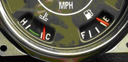
Normally these would be two separate groups of instructions but since these two gauges are so closely interlinked I will furnish explanations for both.
 |
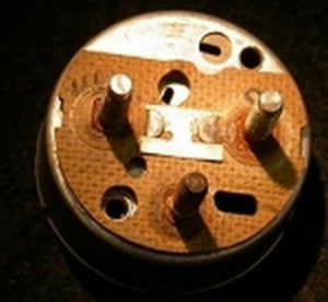
| The Current Regulator |
The heart of the system is the fuel gauge.
This gauge has a built in current regulator that limits the amount of current flowing thru the gauges and sensors. The regulator is simply a strip of bi-metallic metal similar to what you find in your home thermostat. At the end of this strip is a contact that opens and closes as the bi-metallic strip bends.
This contact touches another contact that is connected to the “I” terminal post. There is a thin wire wrapped around the bi-metallic strip that heats the strip as current flows thru the wire. One end of this wire is connected to the contact on the bi-metallic strip and the other end of the wire is connected to the case or ground.
When power is applied, and the strip becomes warm enough, the metal strip bends. This causes the contact at the end of the strip to move and break the connection. Then the current stops flowing and the strip cools down. As soon as it cools then the contacts close and the current starts to flow again and heats up the strip. This is similar to the actions of the turn signal blinker but much faster.
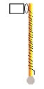 |
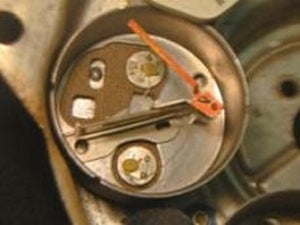
The strip |
You can see it is so quick you need an oscilloscope to view the switching.
One nice thing about this is that as the voltage changes in the Jeep or the temperature changes, the system is self-adjusting so that it will always put out the required amount of current to keep the gauges in calibration.
The power from the regulator goes to the “A” terminal for the temperature gauge and to the other bi-metallic strip that controls the movement of the needle in the fuel gauge.
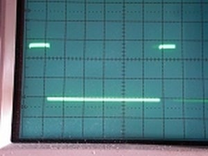 |
| The Oscilloscope Trace |
The indicator part of the gauge also has a wire wrapped tightly around a bi-metallic strip.
 |
| The Bi-metal Strip |
How far the needle move depends upon how hot the bi-metallic bar becomes.
 |
| The bi metallic bar |
This is dependent upon how much power is available from the current regulator and the resistance in the fuel sending unit. When the tank is full, the wiper on the sending unit is at its lowest resistance of approximately 10 Ohms. When the tank is empty the resistance in the tank is around 75 ohms.
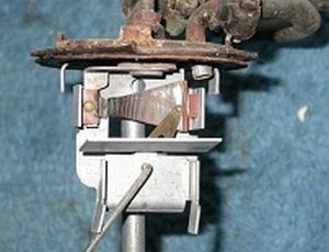 |
| The fuel sender resistance |
In the picture on the left, you an see the wrapping of resistance wire around the trapezoidal insulator.
As the float rises up, the brass wiper moves across these windings changing the resistance as it moves. We won’t get into the trapezoidal shape and its importance in correcting the response of the heating the strip and the arc shape the float moves and the linear response of the gauge. OK? We will note the two limit adjustments on the bottom that limit the motion of the arm to keep it between 10 and 75 ohms.
If you look closely at this picture, it shows signs of overheating. This is probably because the ground connection on the gauge became disconnected at one time when the tank was full.
 |
| The brass contact |
There are several points were the gauge is grounded. The first is a brass contact on the back of the gauge itself. It makes contact with two bumps on the speedometer housing.
The second is the speedometer housing itself. This has to be grounded to the dash usually through the mounting studs.
The temperature gauge is similar to the fuel gauge except it only has a single bi-metallic strip and windings for the needle movement. The movement works on the same principle as the fuel gauge.
This gauge does not have to be grounded for it to work. The ground path is through sensor itself.
 |
| The temp gauge bi-metal strip |
 |
| The temp sender |
The sensor is a temperature sensitive resistor called a Thermistor. As the temperature increases the resistance drops. This causes the windings to heat the bi-metallic strip hotter. On the 258 cu. in. the Temperature sensor is found on the rear of the head, right above the #6 exhaust port. This is probably the hottest part of the engine. If your engine is a replacement engine it might be located on the front of the head just below the thermostat housing.
Continured on Page 2
# # #
|
Off-Road.com Newsletter Join our Weekly Newsletter to get the latest off-road news, reviews, events, and alerts! |
Follow @Off-Road
 Your Privacy Choices