Project 2-4: Getting a 2-Stroke Motor in a 4-Stroke Frame, Part 2

Feb. 14, 2011 By Rick Sieman
In the first part of our project bike, we showed you what we had started with – a YZ 426 rolling chassis that was acquired for $1000 even. This included everything but the engine and the radiators. That's right, frame, forks, wheels, brakes, swingarm and all related plastic parts that come with a full rolling chassis, including handlebars and controls.

 
Read more on Project 2-4, Part 1

For the rather low sum of $225, we were able to get a 1979 Suzuki RM 250 motor, and pipe, in good running condition. We took the motor apart, which is rather easy to do on a two-stroke, and the cylinder looked in good shape. The motor had a stator in it, but it did not have any of the other electrics.

A quick visit to eBay got the missing CDI and coil. The cost for the coil was under 20 bucks and a CDI was about $15. We put everything together once it was received (on a workbench) and lo and behold, we actually had spark.

Our first step was to clean the motor and get the old crud and grit off of all of the little crevices. After the motor was cleaned completely, we hit it with a shot of low-gloss engine enamel. This stuff is not quite flat black and looks pretty good on the motor. When we got done with the paint, the motor looked almost brand-new.

We then turned our attention to actually fabricating motor mounts for the engine and locating the engine in the proper position in the frame. To help us in figuring out exactly where it had to go, we placed the frame on a workbench, and use little one-inch-by-half-inch blocks of wood all under and around the motor to get a good position.

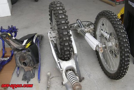
The swingarm and rear wheel complete was bolted into place to give us a reference point for our lineups. The rear sprocket was in place on the YZ rolling chassis and we simply had to line up the countershaft sprocket on the Suzuki motor with the rear sprocket on the YZ to get a starting point.

Here's how we did it:

The low-gloss engine enamel gave a good look to the RM 250 motor.

Everything was bolted back into place, with the proper torque specifications on the head bolts.

All the electrics were hooked up and the motor was kicked through to check for spark. Fortunately, the plug yielded a nice fat blue spark right away.

Small pieces of wood let us position the motor in the frame properly.

With the motor roughly positioned, we made the first motor mount templates out of thin cardboard.

All the engine mounting holes were drilled out to 3/8-inch American size for increased strength. We used grade-5 bolts.

The cardboard template motor mounts were then traced to 1/8-inch-thick metal plate. We decided to use the existing motor mount tabs on the YZ frame rather than weld in new ones. Our goal was to use as few welds as possible.

Two plates were made, one for each side of the motor mounts.

You can see how the motor mount plates mounted into the existing tabs.

The 3/8-inch bolts were then slid home into the motor on both sides.

Here’s the front view of first of the motor mount bolts put in place.

We noticed that the rear motor mount was a bit too wide for the YZ frame for proper clearance, so it was ground down a bit until it cleared properly.

Our attention was then turned to the front motor mounts. As with the bottom motor mounts, we started off with a cardboard template. The 3/8-inch bolt was put through the motor and the template to get a pattern.

This approach was abandoned, as we decided to use the existing frame holes instead of welding the tabs in place. To do this, we drilled out the smaller frame holes to the 3/8-inch American size.

Motor mounts were then made and bolted into place.

Here's a look at the first plate.

The same treatment wasn't done to the shift side of the bike.

A chain was placed over the front and rear sprockets to check for alignment and for correct position of the motor in the chassis.

The rear main motor mount holes were drilled out to take a larger American bolt.

Motor mount plates were fabricated and bolted in place.

The rear motor mount plates were then tack-welded in place.

Since the rear down tubes on the frame were different on each side, the last rear motor mount plate had to be fabricated after the first one was in. It was simple enough to drill a hole and hold the plate in place and then mark it properly.

The plate was completed, taped in place and then tack welded securely.

After ensuring that everything was even, the plate was then welded home.

When the welding was done, everything was dressed up neatly with a small grinder.

The frame was then given a few coats of high gloss engine enamel. This stuff is much tougher than regularly paint and looks real good.

There you go, one sharp-looking frame, ready for motor install … sort of.

The aluminum subframe was also given a coat of paint.

With everything nice and clean, the motor was then very carefully placed into the freshly painted frame. The most important part is next, and that is the side to side alignment of the motor to make sure that it's true with the rear sprocket. We'll take care of that in part three.


Off-Road.com Newsletter
Join our Weekly Newsletter to get the latest off-road news, reviews, events, and alerts!