|
Planning First I decided where I was going to mount the lights, I wanted 2 of them so that I could light the whole area behind the vehicle evenly. The perfect spot for me was the rear rectangular channel underneath the bed, which will allow for the lights to be far enough back without being in the way. Now that the location of the lights was settled, I moved on to determine how I was going to control them with the lever. I pulled out the seats and center cowling to reveal the mechanical workings of the shifting levers. I just happened to have a couple of Cherry snap action switches in my toolbox and when I held them in place, I knew it would work. I’ve got the plan, now I need to locate the supplies, so let’s get started…
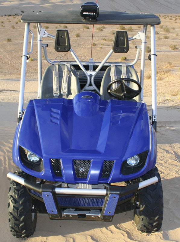
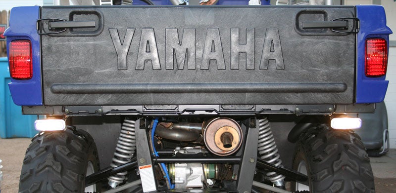
Back-up Lights
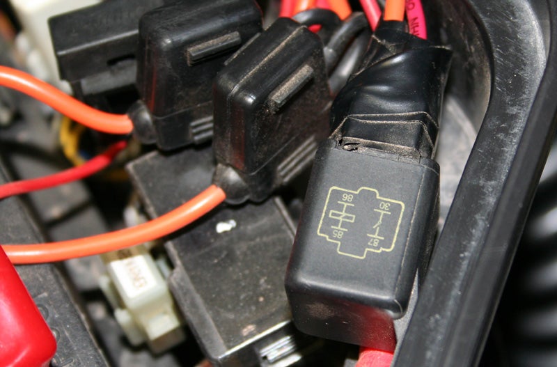
Switches, Fuse, Fuse Holder, and Relay No matter lights you decide to buy, they will need to be on a fused circuit (see ratings listed for your fixture). The fixtures that I chose require a 15 amp fused circuit, so I’ll need a fuse holder and a plug-in fuse rated at 15 amps. Also needed for this project is a 12 volt automotive relay rated for at least what your circuit is fused at(rating for the relay cannot be lower, but it can be higher). This relay will allow the small, low current Cherry switch to control the larger rated lighting circuit. The fuse, fuse holder, and relays are available at most local auto parts stores. Tools & Supplies Before beginning this project it is recommended that you have an assortment of various wire connectors, splices, tape, wire strippers, crimpers, 12 volt/ohm meter, a tube of Dielectric grease, wire ties, and plenty of room to comfortably work.
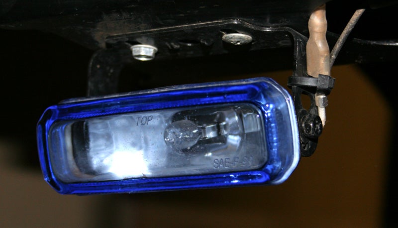
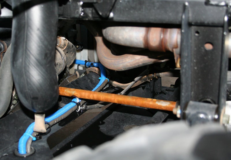
Let The Work Begin Now that I have the supplies for the project, let the work begin… I decided that each of the lights will be mounted at the far ends of the channel with the wiring running through the pre-drilled holes. Since the existing metal was a fairly heavy gauge, I mounted the brackets for the lights by using self tapping hex head screws.
At this point, I set aside the wiring for a moment in order to mount the switch under the shifter on the passengers’ side. First I moved the switch around to a position allowing the rocker arm to activate during reverse without pushing it in too far, and marked the holes with an awl. I then drilled the holes small enough to accept #4 machine screws. Since the switch doesn’t align with the shifting mechanism without a spacer, I used the other Cherry switch to act as a spacer, it works perfectly. I double nutted the machine screws to assure they stayed nice and tight, and then tested the action several times to insure proper alignment, everything looks good, now back to the wiring.
Choose Your Source Depending on when you want the reverse lights to come on, will determine how you want to power the relay for your back-up lights. There are several options to choose from: you can power the relays coil from a constant source of power, meaning that anytime you shift the vehicle into reverse (key on or not) the reverse lights will be on until you shift out of reverse. Second, you can locate a power source that’s on only when the key is on, so when you turn off the key, the reverse lights will go out, even if the vehicle is in reverse. The third option is a source that only has power when the headlights are engaged; meaning that the reverse lights will only work if the key is on, the headlights are on, and the vehicle is in reverse. The choice is yours; whatever best suits you’re needs, but no matter which one you choose, be sure that the coil circuit is properly fused.
Begin Connections Before we connect any wires in the battery box, we’ll return to the reverse switch, and connect the 2 wires to the switch. First, determine (with an ohm meter) which pin in conjunction with common pin creates a normally open condition when the shifter is not in the reverse position. Then, connect one wire to the common pin and the other wire to the other normally open pin. It’s a good idea to use Dielectric grease on all connections to help avoid corrosion.
Connect one end of the fuse holder (without the fuse installed) to the positive battery terminal (with proper connector). Connect the wire on the other end of the fuse holder to one of the normally open pins on the relay. Next, connect the wire coming from the back-up lights to the other normally open pin on the relay. Before installing the fuse and testing lights, re-check all wiring and connections. If your testing is successful you can mount your relay against the inside of the battery box with a bolt and nut through the side. When install is complete, adjust your new back-up lights and enjoy a nice night ride!
Conclusion Before I was willing to share this install with anyone I had to be sure that it would hold up to some abuse, and fortunately it did. I’ve subjected the switches, lights, and the other components to water and dirt, gone through mud, sand, and whatever else I could think of with not one problem. I hope you have enjoyed this install; I’ve got a lot more planned for the future so stay tuned and be safe! Mike Products 12 volt relays:www.pilotautomotive.com Driving Lights, Wire Loom, and Dielectric Grease available at most Auto Parts Stores
|

|
Off-Road.com Newsletter Join our Weekly Newsletter to get the latest off-road news, reviews, events, and alerts! |
Follow @Off-Road
 Your Privacy Choices