|
Turning An Independent Into A Solid-Axle Rock
Crawler
|
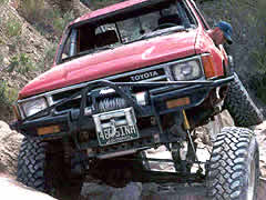
If you're serious about getting maximum suspension flex out of your '86-and-newer Toyota pickup or 4Runner, then you're gonna have to kiss your independent front suspension (IFS) goodbye. You're gonna have to whip out the ol' blue tip wrench and get to slicin' and dicin'! And don't let anybody tell you that an IFS-to-Solid-axle Swap (SAS for short) is a no-sweat deal. It's pretty major suspension surgery that requires skill with both a cutting torch and a welder.
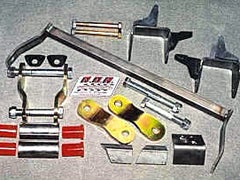 |
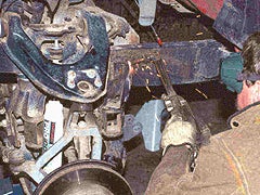
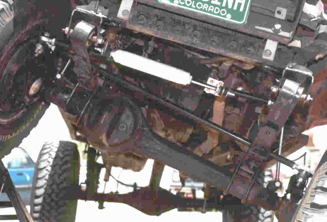
| Here's all that is needed for the swap. |
But most SAS owners will tell you that the major gains in 'wheeling prowess and dexterity are well worth the cost of getting an expert to do the cutting and welding (if you're not an expert yourself). And Advanced Off-Road Research (A.O.R.) offers an IFS Conversion Kit that makes the job just about as easy and straightforward as it can be.
A.O.R.'s Solid-Axle Swap Kit is designed for '86-'95 Toyota trucks and 4Runners, 4-cylinder and V6. The kit includes all the top-quality hardware you see at the upper left for a very reasonable $249.00. You'll need a solid front axle from a '79-'85 Toyota truck or 4Runner (A.O.R. recommends '84-'85). The kit can also be made to work with Dana 44, Dana 60 and other custom axles. You'll retain your stock IFS steering box, but you'll need a new crossover steering system that includes a new drag link, tie rod, pitman arm and new steering arms. And you'll need long-travel shocks and mounts. A.O.R. can fix you up with all these necessary parts and pieces to make your suspension stretch to the max.
Here's a closer look at A.O.R.'s
Solid-Axle Swap Kit and what it takes to install
it.
 |
 |
|
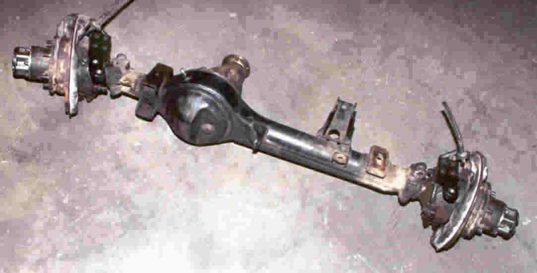
1. First, make
sure you have your front axle on hand. Choices: '79-'85 truck or
4Runner front axle, preferably '84 or '85 due to the extended truss
under the housing. Dana 44s and 60s also work
provided the spring perches are moved to
match Toyota's perch width (29 1/4 inches from center of center-pin
hole to center of center-pin hole).
|
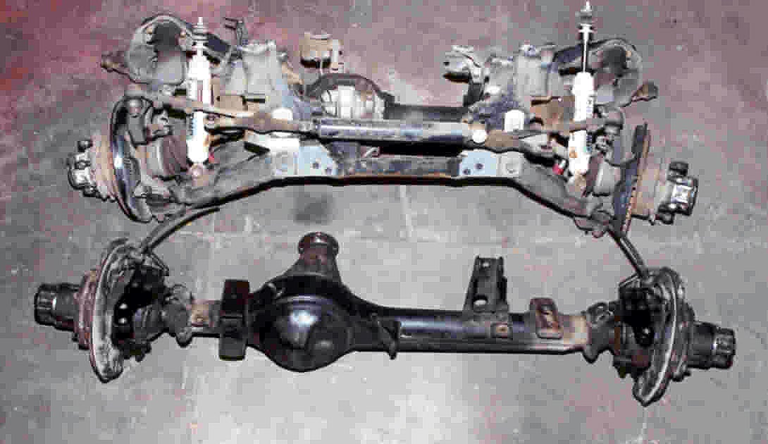
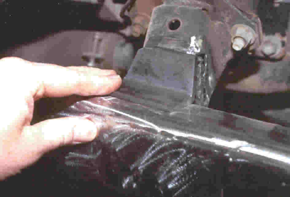
2. The SAS is
basically a matter of surgically removing all the IFS components
from the frame and putting leaf springs in their place.
Luckily, this is not as complicated as it may seem at first. The
IFS assembly attaches to the frame in just two places on each
side. Take out the torsion bars, unbolt some stuff and cut
those four places free--presto, the whole IFS assembly comes off as
one big piece.
|
 |
 |
|
3. To be a
little more precise about "unbolt some stuff," you have to
disconnect steering, torque arm, upper shock studs, sway bar, brake
lines and drive shaft. Remove brake calipers if you plan to reuse
them on the straight axle. A.O.R. can supply the FJ40 rotors you'll
need.
|
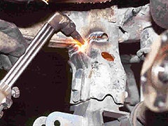
4. With the
A-arm assembly supported from below, and the upper A-arm caps
unbolted, it's time to CAREFULLY start torching off the lower
control-arm bracketry. The trick is not to gouge the frame with the
torch flame.
|
 |
 |
|
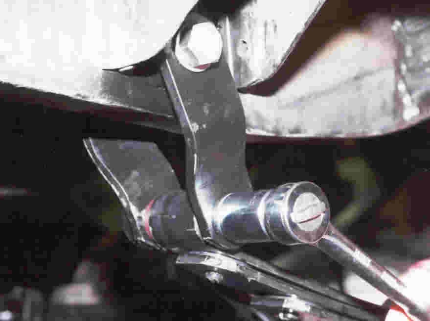
5. Here's the
lower control-arm bracket seen from under truck looking outward.
The entire circumference of the bracket must be torched
off.
|
6. The rear
lower control arm/bumpstop bracket has some internal gussets that
must be torched after the outer cutting is done. Pry bracket
outward to reach the innards.
|
 |
 |
|
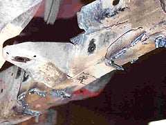
7. Watch your
toes! You'll know you've done all the cutting when the whole
assembly drops. This top-down view shows one side. Other side is
identical.
|
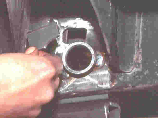
8. Here's the
driver-side frame rail seen from below, looking outward from under
engine. The IFS diff horn is shown still in place. removing it is
optional.
|
 |
 |
|
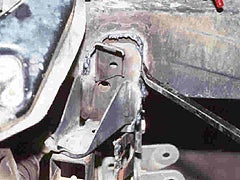
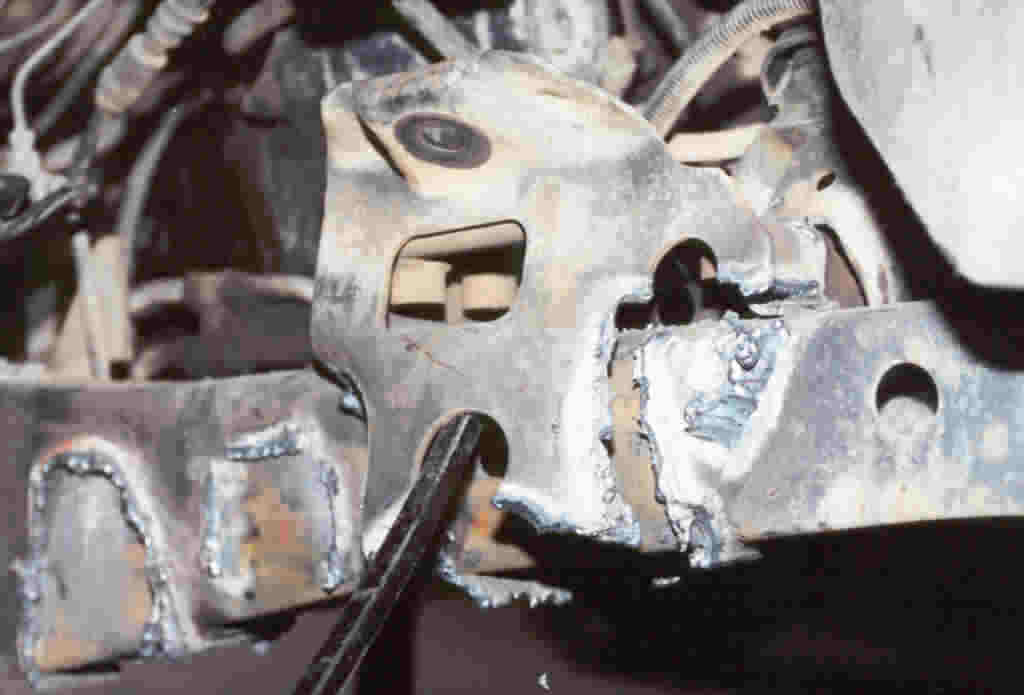
9. Removing the
upper control-arm/upper shock mount is a bit tricky. The
torch cuts around it as shown, but there's a catch: The motor
mounts on both sides are part of this bracket. See photo 10.
The middle cut-off mark shows where the bumpstop bracket was
removed.
|
10. The tricky
part: The motor mounts on both sides are part of the upper
control-arm/shock brackets. When you torch off those brackets, you
must make sure to leave the motor mounts as
shown.
|
 |
 |
|
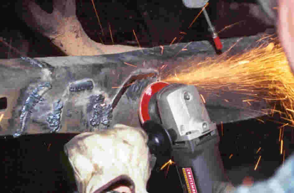
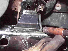
11. Far better to do grinder time than to cut into
the frame with the torch! Besides, grinding like this is
purely for looks--the conversion works just as well whether the
frame is pretty or not.
|
12. A.O.R. Kit's provides angle brackets to
reinforce the motor mounts. The bracket also serves as a
guide to grinding the motor mount. The bracket should have as much
contact as possible for welding.
|
 |
 |
|
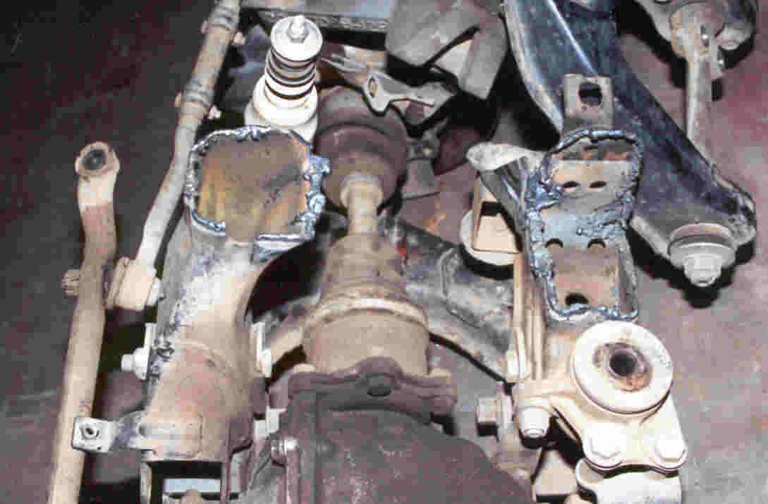
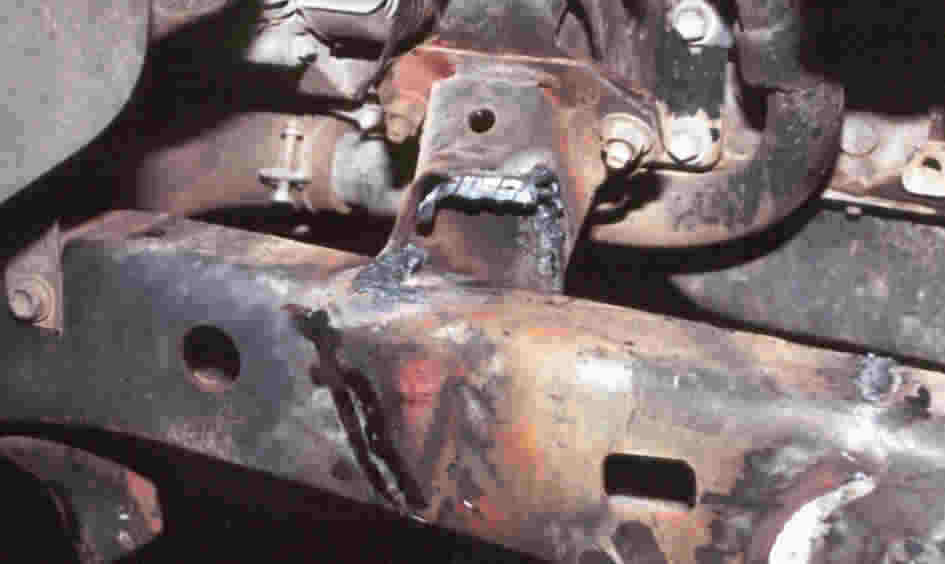
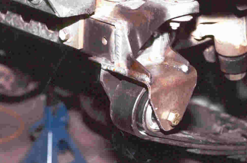
14. Here's a finished view of the frame and boxed
motor mount. Now it's time to graft the the leaf-spring
hangers and shackles onto the frame. This installation assumes
you're using stock-length front springs. But the setup can be
custom-modified to accept longer front springs.
|
15. Position and tack both the angle bracket and
gusset (also included). Then weld both. Repeat process on both
motor mounts.
|
 |
 |
|
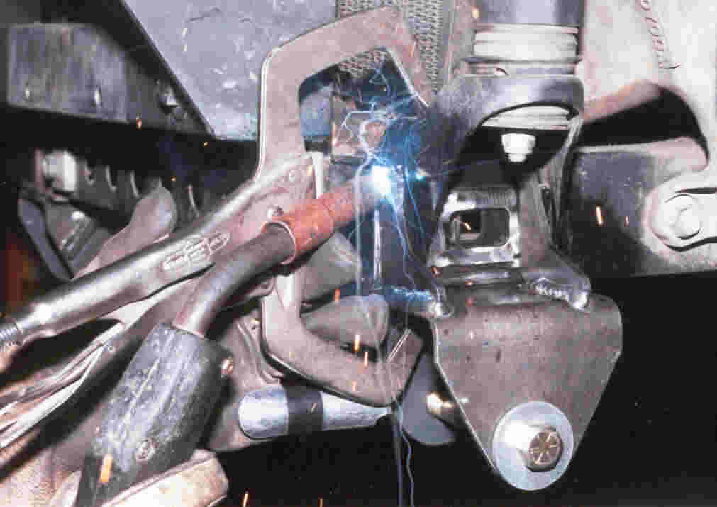
16. A
cool feature of A.O.R.'s SAS kit is that there's no clearance
robbing crossbar between the two front spring hangers. If you're
using A.O.R. Orbit-EyeTM springs, the hangers have
pre-installed gussets that make positioning them on the frame a
snap. For non-Orbit-Eye springs, a removable jig is provided
for easy hanger positioning. At this point, hangers are only tack
welded.
|
17. Prior to finish welding, the best way to check
correct hanger position is to bolt the springs to the solid axle
and trial fit the assembly. The U-bolt Flip Kit shown here is
available from A.O.R. The stock Toy U-bolt setup will only work
with 5-leaf spring packs.
|
 |
 |
|
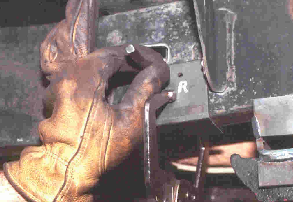
18. Now for the really fun part: drilling the
frame for the upper shackle pivot sleeve. A.O.R. kit includes a
template used to mark the frame with a center punch. Guide
holes are marked L for left (driver side) and R for right
(passenger side).
|
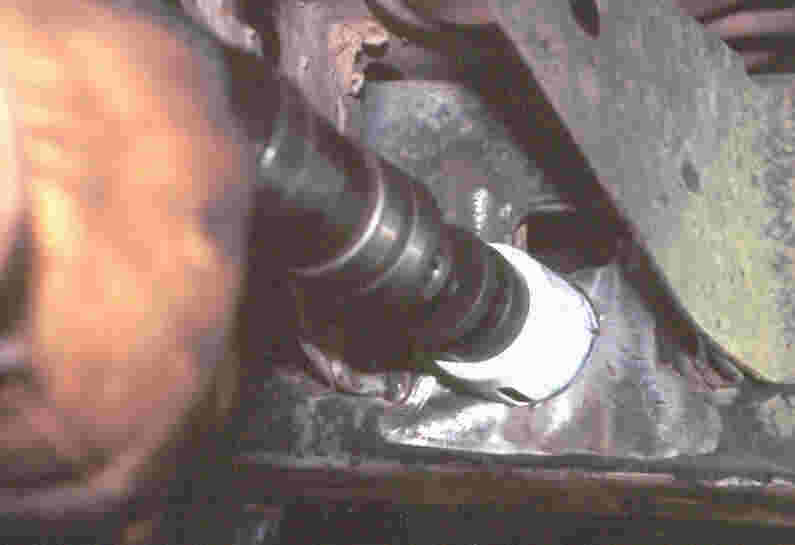
19. Drill the frame using a high quality 1-3/4"hole-saw bit. Try to keep the drill level and square to the frame,
but at this point, you're only drilling through the outer part of
the frame.
|
 |
 |
|
20. There's some webbing inside the frame that must be torched out, then you can drill through the back side of the frame. Now it's important to keep the drill level and square to frame. |
21. Now it's time to assemble and trial-install both-side shackles, sleeves, bushings and jig as shown. All the necessary parts are included in A.O.R.'s kit. Their directions make it easy to position the shackle sleeves correctly for tack-welding. |
 |
 |
|
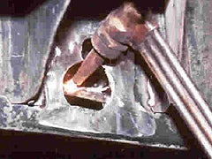
22. After tack welding, you remove the shackles
and bushings and weld the provided cover plate over the square
frame hole as shown.
|
23. Weld the sleeves and cover plates. Don't
forget to weld on the inside of the frame, too!
|
 |
 |
|
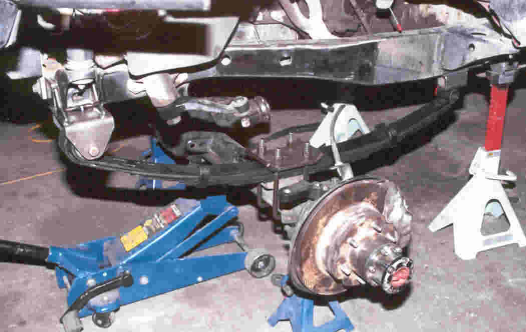
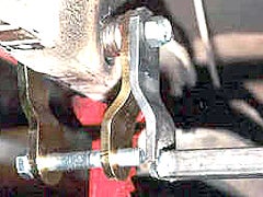
24. Assemble the springs and shackles. It's normal
for the shackles to cant forward slightly when the weight is off
the front end. But both sides should angle about the same.
|
25. A.O.R. recommends finish-welding the front
hangers only after the springs and axles have been bolted in place
and the geometry has been double-checked.
|
 |
 |
|
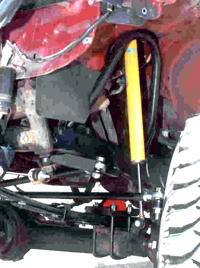
26. A.O.R. recommends waiting until the springs
are completely installed before positioning shocks and mounts.
Contact A.O.R. for all your shock and mounting needs! A.O.R. also
offer crossover steering and extended brake lines.
|
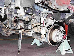
27. It's a good idea to ramp test the finished conversion
before heading for the hills. Check for clearances, adequate brake
line slack, etc.
|
|
Okay, so you can see that an SAS isn't a simple
bolt-on. But talk to 'wheelers who've done the swap.
Bet you won't find a single one who'd rather have his Toy back the
way it was!
|
 |
|
Contact Advanced Off-Road Research
|
Advanced Off-Road Research (A.O.R.)
725-B West Grand Avenue
Grand Junction, CO 81501
970-263-4300 and check out their website and complete online
www.AOR4x4.com
|
Contact Us
|
|
www.Off-Road.com
|